Applications list, Fig.3, Applications chart – Sealey VS001 User Manual
Page 2
AUdI. . . . . . . . . . . . . . . . . . . . . VS001.V3-2, 3, 4 or 7.
AlFA. . . . . . . . . . . . . . . . . . . . . VS001.V3-4.
BMW. . . . . . . . . . . . . . . . . . . . . VS001.V3-4 or 5.
CHRYSleR . . . . . . . . . . . . . . . VS001.V3-8, 7 or 10.
CITROeN . . . . . . . . . . . . . . . . . VS001.V3-7, 8 or 10.
dAeWOO . . . . . . . . . . . . . . . . . VS001.V3-2.
FIAT . . . . . . . . . . . . . . . . . . . . . VS001.V3-6 & 7.
FORd . . . . . . . . . . . . . . . . . . . . VS001.V3-2, 3, 16, 17, 18 or 20.
HONdA. . . . . . . . . . . . . . . . . . . VS001.V3-7, 15 or 16.
HYUNdAI . . . . . . . . . . . . . . . . . VS001.V3-16.
KIA . . . . . . . . . . . . . . . . . . . . . . VS001.V3-13.
lANCIA. . . . . . . . . . . . . . . . . . . VS001.V3-7.
MAZdA. . . . . . . . . . . . . . . . . . . VS001.V3-16.
MeRCedeS . . . . . . . . . . . . . . . VS001.V3-1, 8+10 or 9.
MITSUBISHI. . . . . . . . . . . . . . . VS001.V3-8, 10+14 or 16.
NISSAN . . . . . . . . . . . . . . . . . . VS001.V3-8+10, 8+11+14 or 16.
OPel . . . . . . . . . . . . . . . . . . . . VS001.V3-3, 6, 7 or 16.
PeUGeOT . . . . . . . . . . . . . . . . VS001.V3-6 or 7.
ReNAUlT. . . . . . . . . . . . . . . . . VS001.V3-6, 7.
ROVeR. . . . . . . . . . . . . . . . . . . VS001.V3-5, 6 or 7.
SAAB . . . . . . . . . . . . . . . . . . . . VS001.V3-2.
SeAT . . . . . . . . . . . . . . . . . . . . VS001.V3-3 or 4.
SKOdA. . . . . . . . . . . . . . . . . . . VS001.V3-2 or 3.
SUZUKI . . . . . . . . . . . . . . . . . . VS001.V3-8+11+12 or 8+10 or
. . . . . . . . . . . . . . . . . . . . . . . . .
8+11+14.
TOYOTA . . . . . . . . . . . . . . . . . . VS001.V3-8+11+14 or 15.
VAG . . . . . . . . . . . . . . . . . . . . . VS001.V3-2, 3, 4 or 7.
VOlVO . . . . . . . . . . . . . . . . . . . VS001.V3-6 or 7.
APPLICATIONS LIST
4. APPLICATIONS CHART
3.2.
CHECKING THE SYSTEM.
NOTE: Due to the design of the internal pump seal, a vigorous
pumping action is required to activate the seal and
pressurise the system. A light or slow pumping action
will prove ineffective. The larger the air space within the
cooling system being tested, the more vigorous the
initial pumping should be. By filling the cooling system
and therefore reducing the airspace within, less effort
will be needed to pressurise it.
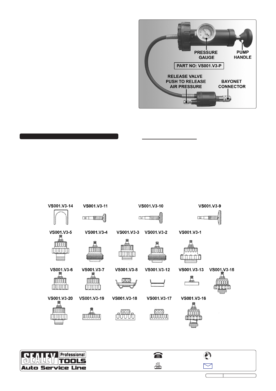
3.2.1. Pump the system until the pressure gauge (fig.3) indicates
approximately 15 psi.
3.2.2. If gauge pointer remains stationary for one minute it will
indicate that the cooling system is in good working order.
3.2.3. If the pointer falls, it indicates that the system has a leak
resulting in loss of pressure.
3.2.4. Check the system for water leaks and, if located, repair
accordingly.
3.2.5. If there is pressure loss but no external water leakage check
condition of the head gasket.
3.2.6. Re-test to ensure the repaired system is in good working
order.
Note! To release pressure from the pump, press the release valve
(fig.3). ensure the gauge is reading zero to indicate no
pressure before disconnecting.
fig.3
VS001.V3 Issue No.2 13/04/12
Original Language Version
NOTE: It is our policy to continually improve products and as such we reserve the right to alter data, specifications and component parts without prior notice.
IMPORTANT: No liability is accepted for incorrect use of this product.
WARRANTY: Guarantee is 12 months from purchase date, proof of which will be required for any claim.
INFORMATION: For a copy of our latest catalogue and promotions call us on 01284 757525 and leave your full name and address, including postcode.
Sole UK Distributor, Sealey Group,
Kempson Way, Suffolk Business Park
,
Bury St. edmunds, Suffolk,
IP32 7AR
01284 757500
01284 703534
www.sealey.co.uk
Web