Fig.1, Fig.2, Introduction & specification – Sealey SM27 User Manual
Page 3: Contents & assembly, Set-up and operation
2.1. Introduction
Quality workshop lathe suitable for a wide range of turning and drilling applications. features power feed for even surface finish and thread
cutting. four-way tool post mounted on compound slide mechanism enables fast interchange of cutting tools with accurate feed. Powered by
550Watt motor through a six-speed gearbox. Incorporates quiet-running Pto gearbox with oil bath lubrication for power feed. Supplied with
three-jaw chuck and dead centre. fitted with no-load voltage release switch. Meets Supply of Machinery (Safety) regulations 1992 (and
amendments). Workshop stand available as an optional extra, Model no. SM27St.V2.
2. INTRODUCTION & SPECIFICATION
Motor ...................................................... 550W - 230V 50Hz
Spindle Speed range ......................................160-1600rpm
distance Between centres ........................................ 500mm
centre Height over table ......................................... 150mm
centre Height over Saddle ......................................... 80mm
Spindle Bore ............................................................... 26mm
Headstock taper. . . . . . . . . . . . . . . . . . . . . . . . . . . . . . Mt4
tailstock taper . . . . . . . . . . . . . . . . . . . . . . . . . . . . . . . .Mt3
tailstock travel. . . . . . . . . . . . . . . . . . . . . . . . . . . . . . 40mm
Screw cutting:
Metric Pitches. . . . . . . . . . . . . . . . . . . .14 in range 0.5-3mm
Imperial Pitches . . . . . . . . . . . . . . . . . . 20 in range 11-40tpi
2.2. Specification:
DO NOT use the lathe for a task it is not designed to perform.
DO NOT allow untrained persons to operate the lathe.
DO NOT get the lathe wet or use in damp or wet locations or areas where there is condensation.
WARNING! DO NOT use the lathe where there are flammable liquids, solids or gases such as petrol, paint solvents, waste wiping rags etc.
DO NOT operate the lathe if any parts are missing or damaged as this may cause failure and/or personal injury.
DO NOT lift or remove the chuck guard whilst the lathe is in use.
DO NOT touch the workpiece close to the cut as it will be very hot. Allow to cool.
DO NOT leave the lathe running unattended.
DO NOT operate the lathe when you are tired or under the influence of alcohol, drugs or intoxicating medication.
When not in use switch off the lathe and isolate from the power supply.
3. CONTENTS & ASSEMBLY
3.1. Contents:
lathe
face Plate
three-jaw (Internal) chuck and chuck Key
external chuck Jaws
centres, Mt3 & Mt4
Gear Set, thread cutting, 13pc (Metric)
drive Belts, 2 Short, 1 long
4 Hex Keys, 4, 5, 6 & 8mm
2 Spanners, 8x10mm & 17x19mm
WARNING! Safe handling will require two people.
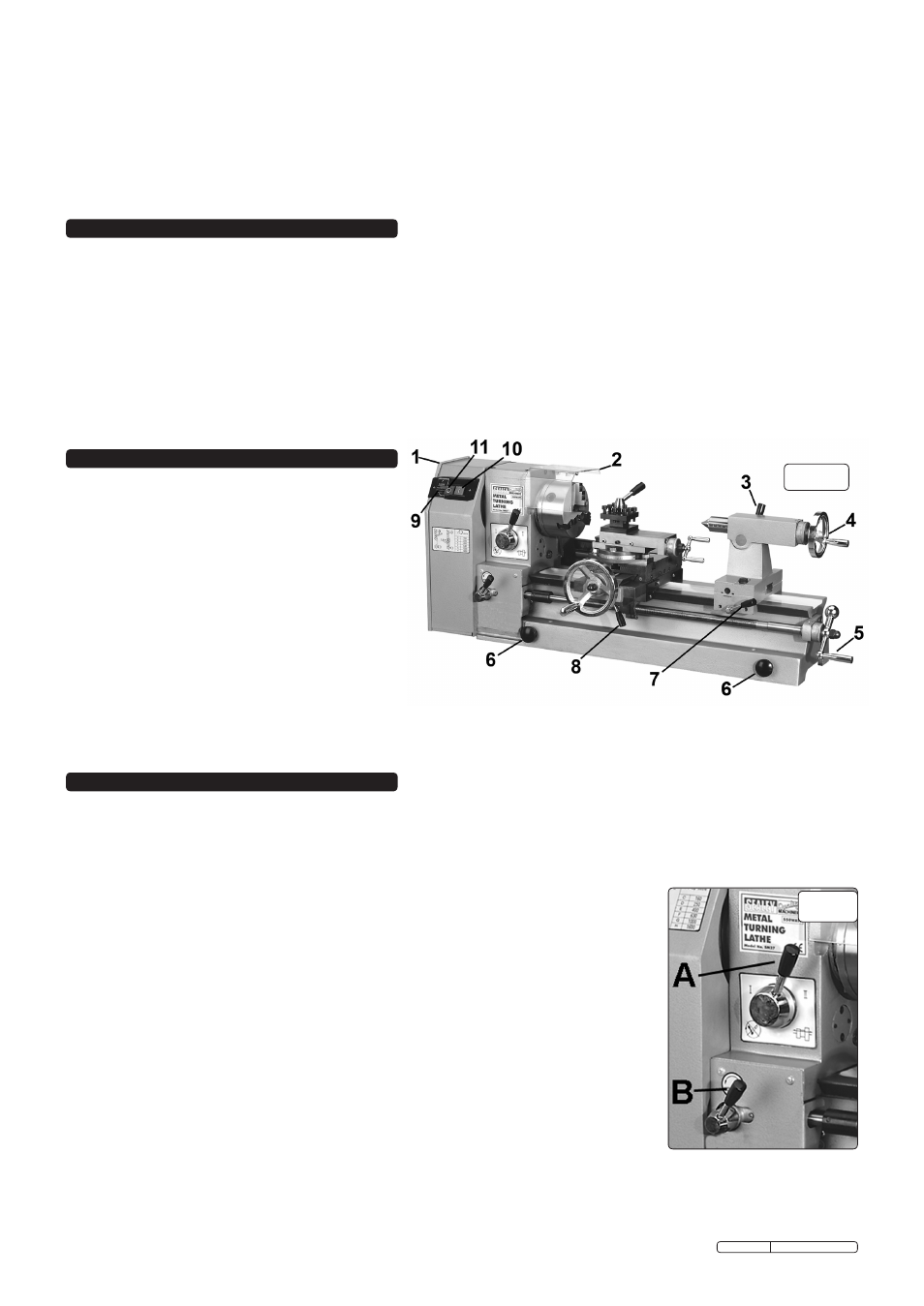
Note that the lathe has four pull-out handles (fig.1.6)
to aid lifting.
3.2. Assembly
3.2.1. unpack the product and check that all components and tools are
present and undamaged. If any problem is noted contact your supplier immediately.
3.2.2. the machine has been coated with grease to protect it in shipping. remove the coating
with commercial degreaser, kerosene or similar solvent before use. After degreasing coat the machined surfaces with machine oil.
3.2.3. Position the lathe on a sturdy workbench or on the optional stand (Model no. SM27St.V2). the lathe should be bolted directly to the
workbench or stand through the four holes provided in the bed.
fig.1
4. SET-UP AND OPERATION
It is assumed that the operator has experience of machining practice and these instructions are intended only to describe the features
of the lathe. If you have no experience of machining it is recommended that you undertake training before using this machine.
WARNING! Before operating the lathe ensure that you are wearing approved safety goggles and gloves to protect you from swarf
and metal particles. If using cutting oil or coolant a face mask may be necessary to avoid breathing any vapour generated. Ensure that
all other safety instructions in Section 1 are followed carefully.
4.1. Initial start-up
4.1.1. check that the forward/reverse switch is in the forward position (fig.1.9) and that the leadscrew
lever (fig.2.A) is on zero.
Note that the forward/reverse switch must only be changed when the lathe is switched off.
4.1.2. Set the automatic feed lever (fig.2.B) to disengaged - turn clockwise.
4.1.3. confirm that the cross slide is well clear of the chuck and that all keys, spanners etc. are clear of
the machine. Move the cross slide along the lathe bed by turning leadscrew handle (fig.1.5).
4.1.4. connect the lathe to the mains supply.
4.1.5. lower the chuck guard.
Note that the lathe will only operate with the chuck guard lowered.
4.1.6. Switch on the lathe by pushing the green switch (fig.1.10).
4.1.7. for this initial start-up run the lathe for about five minutes.
4.1.8. Switch off the lathe by pressing the red switch (fig.1.11). disconnect from the mains supply.
4.1.9. check that nothing on the lathe has worked loose and that the mounting bolts are secure.
4.2. Headstock
the headstock spindle has an Mt4 taper (internal) for the face plate or a spindle centre (see
Accessories Section).
4.3. Tailstock
the tailstock spindle has an Mt3 taper (internal) for a centre or chuck. See Accessories
Section for the rolling centre and tailstock chuck. the spindle is positioned using the feed handle
(fig.1.4) and then locked with the locking handle (fig.1.3).
the tailstock base may be moved along the lathe bed as necessary and locked in position by
the locking lever (fig.1.7).
fig.2
Original Language Version
SM27.V2 Issue: 1 - 06/02/12