Fig.8 fig.7 fig.9 fig.6 – Sealey SM3002 User Manual
Page 4
Thread
Gear Size (Teeth)
Pitch
A
B
C
D
Dial
0.4
20
50
40
60
1, 3, 5 or 7
0.5
20
50
-
60
Any
0.6
40
50
30
60
Any
0.7
40
50
35
60
1, 4 or 5
0.8
40
50
40
60
1 or 5
1.0
20
60
-
30
Any
1.25
50
40
-
60
1, 3, or 5
1.5
40
60
-
40
Any
1.75
35
60
-
30
1, 4 or 5
2.0
40
60
-
30
Any
Turning 20
80
20
80
-
fig.8
fig.7
fig.9
fig.6
4.1.4. connect the lathe to the mains supply.
4.1.5. Move the forward/reverse switch (fig.3.B) to forward and then release the emergency stop switch (fig.3.c) by pushing the red cover
up in the direction of the arrow.
4.1.6 Move the chuck guard (see fig.1.1) down over the chuck.
NOTE: The lathe will not start if the chuck guard is left in the up position.
4.1.7. Switch on the lathe by slowly turning the speed control (fig.3.A) clockwise.
4.1.8. for this initial start-up run the lathe for about five minutes, gradually increasing the speed up to its maximum. run at maximum for a
further two minutes.
4.1.9. Switch off the lathe by turning the speed control (fig.3.A) anti-clockwise to zero and then moving the forward/reverse switch (fig.3.B)
to off. disconnect from the mains supply.
4.1.10. check that nothing on the lathe has worked loose and that the mounting bolts, if used, are secure.
4.1.11. repeat the above running and checking but with the high/low range lever in the High position.
4.2.
Headstock
the headstock spindle, which is belt driven, has a flange with mounting holes
for chuck etc. and a number 3 Morse taper (internal) for a spindle centre
(see Accessories Section) .
4.3.
Tailstock
the tailstock spindle has a number 2 Morse taper (internal) for a centre or
chuck. A plain centre is provided. See Accessories Section for the rolling
centre and tailstock chuck. the spindle is positioned using the feed handle (fig.1.3)
and then locked with the locking handle (fig.1.2).
the tailstock base may be moved along the lathe bed as necessary and
locked in position by the clamping nut (fig.1.4).
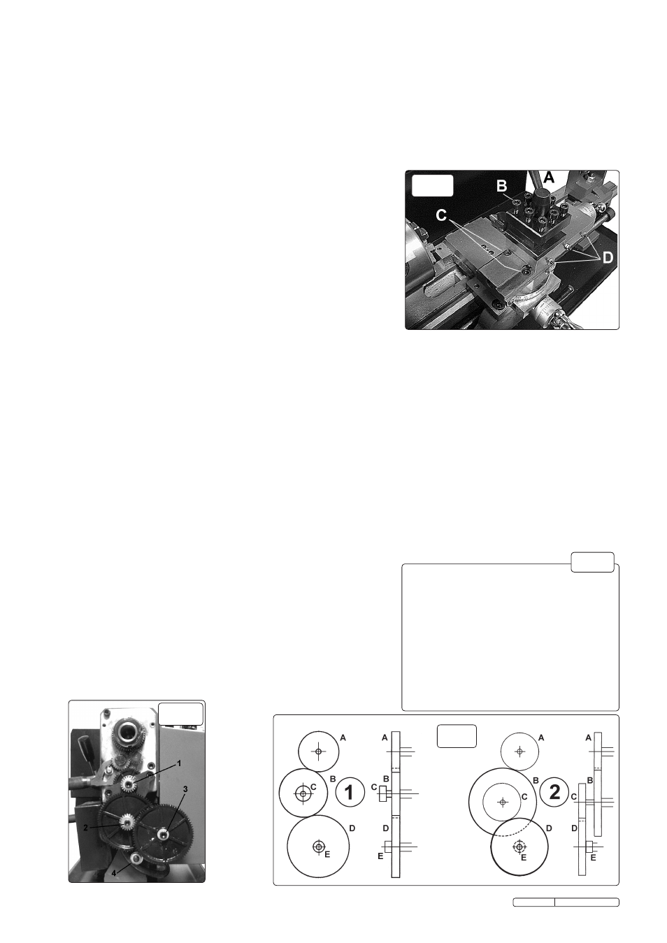
4.4.
Tool Rest
up to four tools can be mounted on the tool rest. the rest can be rotated, in
90° steps, by slackening the locking handle (fig.6.A), and slightly lifting the
rest.
Always ensure that the locking handle and tool clamp screws (fig.6.B)
are tight before starting to cut.
the tool rest is mounted on the compound slide, which in turn is mounted on the cross slide. the compound slide can be rotated ±45°
on the cross slide to permit
bevel and taper cutting. to rotate the compound slide, wind the tool rest fully to the right to reveal the two
clamp screws (fig.6.c). loosen the clamp screws, rotate the slide to the required angle and then tighten the clamp screws.
4.5.
Chuck
the chuck is supplied with internal jaws fitted and a set of external jaws. to remove and fit jaws proceed as follows:
using the chuck key, fully wind out the fitted jaws, at which point they can be pulled from the chuck.
the thread segments on the jaws are staggered and therefore the jaws are numbered 1 to 3 and must be fitted in this sequence, in an
anti-clockwise direction (facing the chuck).
turn the chuck key anti-clockwise while watching the chuck thread in one of the jaw slots. When the end of the thread has just cleared
the slot stop turning the key and insert jaw 1 into this slot. Insert the other two jaws in the other slots in sequence. Hold them under light
pressure whilst turning the key clockwise until they are picked up by the thread and start to move inwards.
check that the three jaws come together correctly at the centre of the chuck. If not, repeat the procedure.
WARNING! Before starting the lathe always confirm that nothing will contact the chuck by rotating the chuck by hand with the
tool rest as far to the left as it will be during the turning operation. Make sure that the chuck guard is in place, as shown in fig.1.1.
4.6.
Turning
4.6.1. Mount the cutting tool in the tool rest such that the tip of the tool is level with, or just below, the lathe centre line. check this by aligning
the tool tip with the point of the tailstock.
The tool tip must not be above the centre line. the height of the tool tip may be adjusted by
shimming or grinding the tool.
4.6.2. Mount the workpiece in the chuck and if necessary, support the other end with the tailstock. Steady and follow rests are also available,
see Accessories Section.
4.6.3. Set the speed range, forward/reverse control and autofeed lever to suit the job.
4.6.4. Start the lathe by slowly turning the speed control clockwise until the required
turning speed is reached.
4.7.
Turning with auto feed
4.7.1. Proceed as in 4.6. but in 4.6.3. also set the lead screw lever (fig.4.B) to forward.
4.7.2. Position the tool just to the right of the end of the workpiece, start the lathe and
adjust the speed control knob to achieve the desired turning speed.
4.7.3. Push down the auto feed lever (fig.5.A) to engage the lead screw. the tool
will now move to the left and begin cutting.
4.7.4. Be ready to disengage the leadscrew when the tool reaches the end of the cut.
DO NOT allow the tool to over-travel and come into contact with the chuck.
Always be prepared to hit the emergency stop button if the leadscrew cannot
be disengaged.
Original Language Version
SM3002.V2 Issue: 4 - 13/02/12