Maintenance, Operating instructions – Sealey SM521 User Manual
Page 3
5.1
PRE-USE INSPECTION
WARNING! INSPECT THE GRINDER BEFORE OPERATING THE MACHINE. ENSURE THE GRINDER IS UNPLUGGED FROM
THE MAINS POWER BEFORE COMMENCING THE INSPECTION.
5.1.1 Check the tool rest on the dry wheel is securely fixed and set at a maximum of 2mm from the grinding stone.
5.1.2 Check that eye shield is in good condition, secure and that you can see through it clearly.
5.1.3 Turn the dry grinding stone by hand and check for any damage. Check they do not touch the tool rest or guards and are correctly
aligned.
If any of the above checks fail, replace, repair, or adjust as necessary before starting the grinder.
5.2
STONE USE
Depending on the model, grinders are supplied with one or two aluminous oxide stones. Stones have two grades, fine for hard
materials and coarse for soft materials.
When grinding, should surface of the stone become “loaded” (coated with particles of the material being ground) it is probably the
wrong grade of stone for the job.
IMPORTANT: Grinding stones MUST ONly be assembled by a person holding a grinding wheel certificate. See section 4.
5.3
USING THE GRINDER
WARNING! Before commencing work, ensure you have read, understood, and apply the chapter 1. Safety Instructions
5.3.1 Plug the grinder into the mains power supply.
5.3.2 Place the eyeshield in its appropriate safety location.
5.3.3 Switch the grinder on and bring the workpiece slowly into contact with the spinning stone, or wire wheel.
5.3.4 When you have completed your task, unplug the grinder from the mains power supply, and clean the machine ready for next use.
6. MAINTENANCE
WARNING! Ensure the grinder is unplugged from the mains power supply before performing any maintenance or service.
6.1
As the grinding stone wears, adjust the position of the tool rest. The rest must be set at a maximum of 2mm from the stone surface.
6.2
Regularly remove the grinding stone covers and clean out any dust and dirt.
6.3
The machine motor and bearing are sealed units and require no regular maintenance. Should you require assistance, contact your
local Sealey service agent.
6.4
For information relating to the handling and maintenance of grinding stones refer to section 4.
4.2
DRY STONE CHANGING PROCEDURE
WARNING!
Unplug grinder from the mains power supply before changing stone.
4.2.1 Remove three cross head machine screws and nuts from wheel cover and remove cover.
4.2.2 Hold grinding stone firmly. To protect your hands use cloth or wear gloves. Unscrew retaining nut (Fig.2).
Note: The 19mm A/F nut on the wet and dry grinding wheels are standard right hand thread (undo anti-clockwise). It may be necessary to
strike the wrench sharply in the loosening direction with the heel of your hand to loosen the nut.
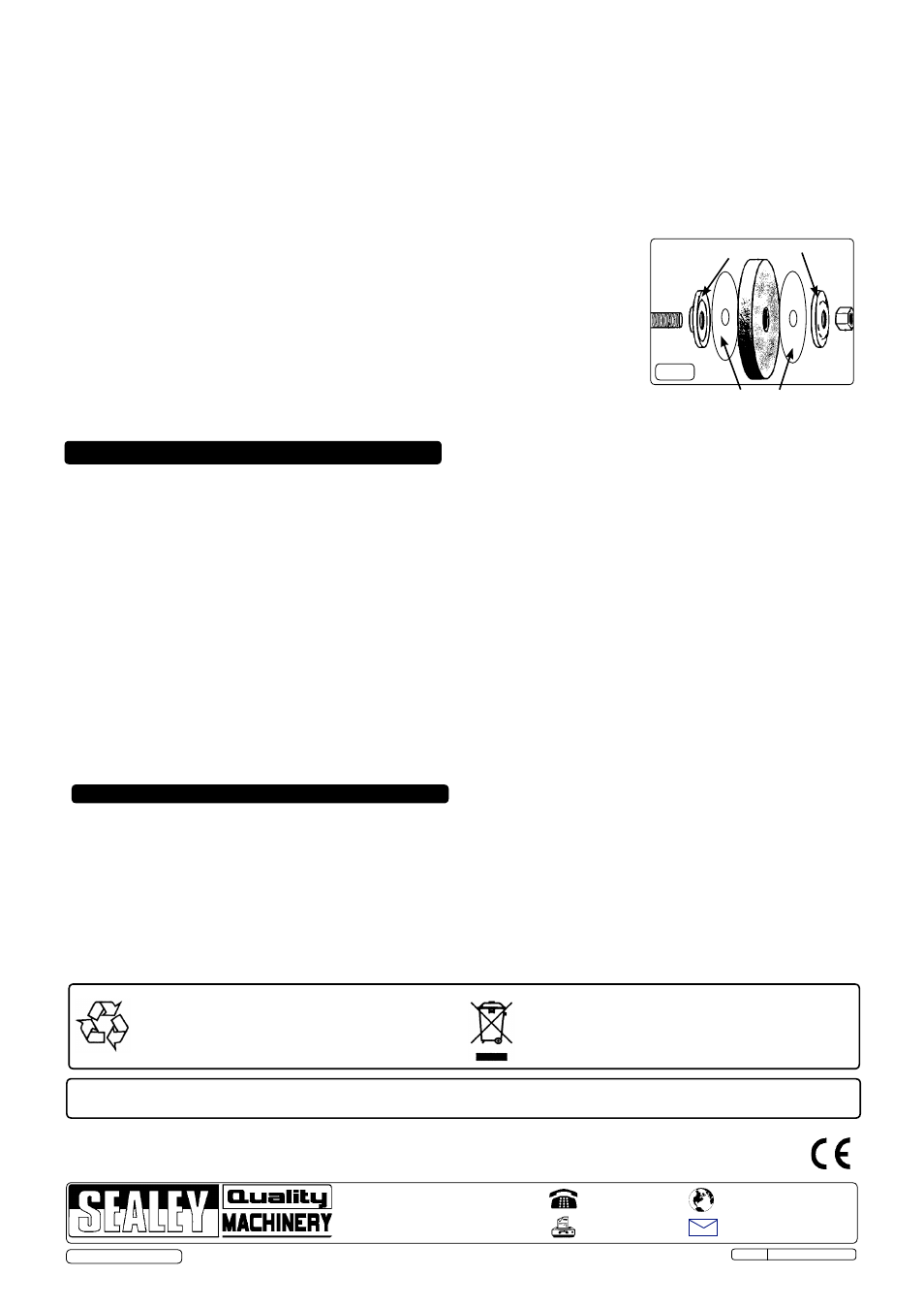
4.2.3 Remove the grinding stone (Fig.4), from main spindle (dry stone), or worm spindle (wet stone).
4.2.4 Carefully inspect the new stone before installing to ensure there are no fissures, chips, or cracks.
Tap the grinding wheel gently with a rubber mallet and listen for a sustained high pitch (good) or
dull short sound (flawed).
WARNING! DO NOT USE A DAMAGED STONE OR WITHOUT SUPPlIED BlOTTERS.
4.2.5 Inspect the blotters, if they are damaged replace them. The grinder must never be used without
blotters. Use the blotters supplied by the wheel manufacturer only.
4.2.6 Install the new stone by reversing steps above. Ensure the domed washers are installed with
the flange on the inside, (i.e. the concave side against the blotter).
4.2.7 Hold stone steady and secure locking nut.
DO NOT over tighten as this may crack the stone.
4.2.8 Replace stone cover, re-adjust tool rest to a maximum of 2mm from stone face and tighten
securely.
4.3
WET STONE CHANGING PROCEDURE
4.3.1 Slacken two cross head machine screws and nuts on wheel cover top and one hexagon head
screw and nut at the bottom of the cover.
4.3.2 Four tabs at the top of the plastic cover can be forced off the ledge and the cover can be removed
vertically downward, see Fig.3. The bottom screw and nut will also now be removed.
4.3.3 Follow points 4.2.2 to 4.2.7 and finally refit the cover.
5. OPERATING INSTRUCTIONS
NOTE: It is our policy to continually improve products and as such we reserve the right to alter data, specifications and component parts without prior notice.
IMPORTANT: No liability is accepted for incorrect use of this product.
WARRANTY: Guarantee is 12 months from purchase date, proof of which will be required for any claim.
INFORMATION: For a copy of our latest catalogue and promotions call us on 01284 757525 and leave your full name and address, including postcode.
01284 757500
01284 703534
Sole UK Distributor, Sealey Group,
Kempson Way, Suffolk Business Park
,
Bury St. Edmunds, Suffolk,
IP32 7AR
www.sealey.co.uk
Web
Original Language Version
© Jack Sealey Ltd
Fig.4
Blotters
Domed washer orientation
SM521 Issue: 1 - 07/12/12
Parts support is available for this product. To obtain a parts listing and/or diagram,
please log on to www.sealey.co.uk, email [email protected] or telephone 01284 757500.
Environmental Protection.
Recycle unwanted materials instead of disposing of them as
waste. All tools, accessories and packaging should be sorted,
taken to a recycle centre and disposed of in a manner which
is compatible with the environment.
WEEE Regulations.
Dispose of this product at the end of its working life in compliance
with the EU Directive on Waste Electrical and Electronic Equipment.
When the product is no longer required, it must be disposed of in an
environmentally protective way. Contact your local solid waste
authority for recycling information.