Fig.3, Operating instructions, Maintenance – Sealey SJBEX200 User Manual
Page 2
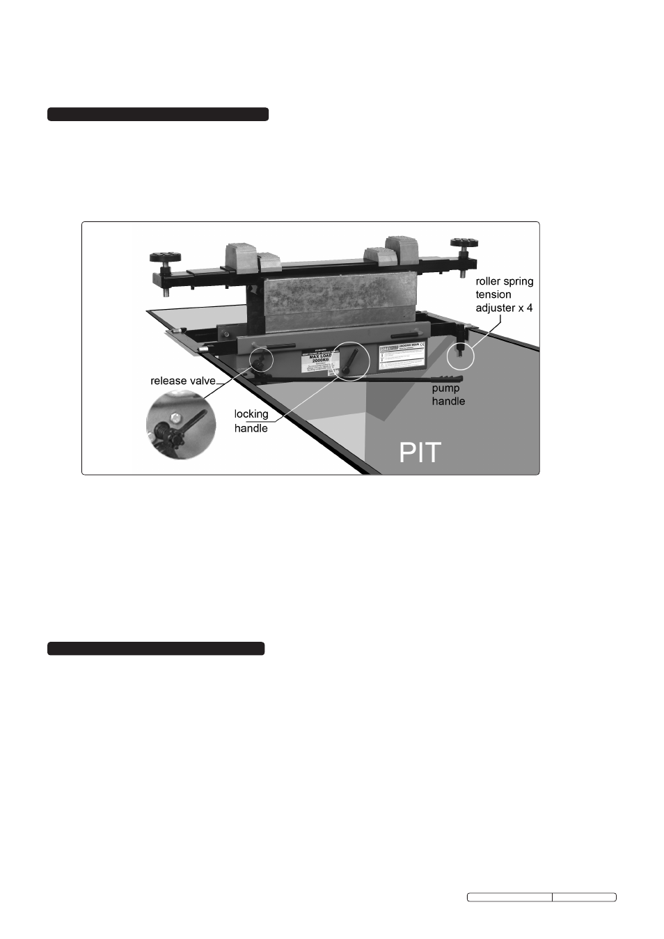
4. oPERAtING INStRuCtIoNS
4.1.
Jacking beam controls (fig.3).
4.1.1. Familiarise yourself with the controls of the jacking beam before operating.
Note: The further anticlockwise you turn the release valve the faster the beam will lower. Familiarise yourself with this before operating
under load.
4.1.2. As a safety feature the beam has two locking positions which are controlled by the locking lever.
4.1.3. When jacking, the locking lever will engage at certain heights (approx 100mm and 240mm of lift height) to prevent the jack from
lowering all the way should the release valve be accidentally moved, to lower the jack past this point you must raise the jack a small
amount and then turn the locking lever clockwise whilst turning the release valve anticlockwise.
fig.3
s
ImpoRTANT: only fully qualified personnel should attempt maintenance or repair.
5.1.
When not in use, the beam should be stored in the lowest position, to minimise corrosion.
5.2.
Keep the beam clean and lubricate all moving parts on a regular basis.
WARNING: do Not use brake fluid, or any fluid other than a good quality jack oil, such as SEALEy hydRAuLIC JACK oIL,
as this may cause serious damage to the jack and will invalidate the warranty!
5.3.
to check on fluid level and to top up, jack the beam up so that the vent valve (see Fig.1) can be accessed and removed . lower the
beam fully and then check on the fluid level either directly or using a dipstick. the level should be just below the vent, top up as
necessary and do Not overfill as this will affect the smooth operation of the beam. replace the vent valve.
5.4.
Before each use check for broken, cracked, bent, or loose parts, or any visible damage to pump, saddles, lifting arms, frame and all
parts including nuts, bolts, pins and other fasteners. If any suspect item is found, remove beam from service and take action to
remedy the problem. do Not use the beam if it is believed to have been subjected to abnormal load or shock load. Inspect and take
appropriate action.
5.5.
Periodically check the pump piston and the ram for signs of corrosion. clean exposed areas with a clean oiled cloth.
s
ImpoRTANT: No RESpoNSIBILITY IS ACCEpTED FoR INCoRRECT USE oF THIS pRoDUCT.
Hydraulic products are only repaired by local service agents. We have service/repair agents in all parts of the uK.
Do NoT RETURN jACkS To US. Please telephone us on 01284 757500 to obtain the address and phone number of your local agent.
If jack is under guarantee you can also contact your local dealer.
de-commissioning
If the beam eventually becomes unserviceable, draw off the oil into an approved container and dispose of the jack and the oil
according to local regulations.
5. MAINtENANCE
4.2.
to jack a vehicle.
4.2.1. With the beam in the lowered position, locate it under the vehicle at the position that you require to lift.
Note: Ensure you use the vehicle manufacturer’s designated jacking points.
4.2.2. the majority of lift applications require the use of two saddles.
4.2.3. Evaluate which saddle pair combinations are best suited to the job.
4.2.4. the saddles at either end are adjustable, and may be raised or lowered by screwing clockwise or anticlockwise in order to give the
beam clearance from the underside of the vehicle.
4.2.5. Adjust the telescopic arms to line up the saddles with the jacking points of the vehicle.
4.2.6. turn the release valve clockwise and start to raise the jack by operating the pump handle (Fig.3). raise the beam in short increments
and ensure the saddles are centered on the jacking points.
4.2.7. once you have established the setup is stable you may proceed to lift the vehicle to the required height.
4.2.8. Make sure the locking lever is engaged, if it is not engaged you need to raise or lower the beam to the closest locking point,and check
the locking lever engages.
4.2.9. to lower the vehicle follow the procedure outlined in 4.1.3 Jacking Beam controls.
3.2.
using hook arm supports.
3.2.1. Alternative hook arm supports are supplied for use where the runners on a ramp or pit are vertical (see fig.4). Loosen the roller arm
set bolts (see fig.2) and withdraw the roller arms from the main frame. Insert the hook arm supports ensuring that the channel faces
downwards and set them to match the width of the vertical runners. the hook arm supports should be extended equally either side of
the jacking beam. tighten all four support arm set bolts before mounting the jacking beam onto the runners.
Original Language Version
SJBEX200.V2, SJBEX300 Issue: 4 - 16/10/09