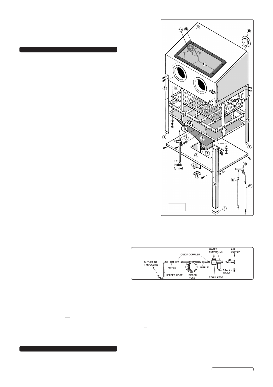
Fig 1, Assembly & installation 4. operating instructions – Sealey SB973 User Manual
Page 2
3.2
Air Supply. For recommended hook-up, see diagram to below.
3.2.1 You will require an air pressure of 90psi, and an air volume of 15cfm max for operating the unit.
WARNING! Ensure air supply does not exceed 90psi. Too high an air pressure and unclean air will shorten the product life
due to excessive wear, and may be dangerous causing possible damage and/or personal injury.
3.2.2 The air supply must be clean and dry. Drain the air supply tank daily. Water in the air line will damage the item being blasted and will
invalidate the warranty.
3.2.3 Clean the air inlet filter screen weekly.
3.2.4 Line pressure should be increased to compensate for
unusually long air hoses (over 8 metres). The minimum
hose diameter should be 10mm I.D. and fittings must
have the same inside dimensions.
3.2.5 Keep hose away from heat, oil and sharp edges. Check
hoses for wear. Make certain all connections are secure.
Capacity . . . . . . . . . . . . . . . .0.22m³
Maximum air flow . . . . . . . . . 15cfm
Air Pressure . . . . . . . . . . . 60-90psi
Air inlet size . . . . . . . . . . . .1/4”BSP
Overall height . . . . . . . . . . 1380mm
Overall width. . . . . . . . . . . . 890mm
Depth . . . . . . . . . . . . . . . . . 570mm
Doors . . . . . . . . . . . . . . . . . . . . . . 1
Extraction Port Ø . . . . . . . . . 60mm
Viewing Area. . . . . . . 570 x 270mm
3.1
Assembly. (This cabinet should be assembled by two people).
3.1.1 Unpack the product and check contents. Should there be any damaged or
missing parts contact your supplier immediately.
3.1.2 Protect the cabinet (fig.1-3) from scratches and lay it on its side.
3.1.3 Push trim moulding (1) onto the bottom of each leg (2).
3.1.4 Attach the four legs (2) to cabinet (3) by passing screws from outside and
finger tighten with nuts on the inside of the cabinet.
3.1.5 Carefully peel backing paper from the foam sealing strip and lay the exposed
sticky surface all around the upper rim of funnel (fig.1-T1). Trim as required
ensuring there are no gaps. Make holes in foam where screws are to go.
3.1.6 Also apply a layer of foam sealing tape all around the underside edge of the
main cabinet. See fig.1-T2.
3.1.7 Also apply tape to the sealing surfaces of the door if not already applied.
3.1.8 Bolt the suction tube (7) to the inside of the front surface of the funnel (5).
3.1.9 Place the screen frame (12) on top of the funnel ensuring that the mounting
holes line up.
3.1.10 Sit the wire mesh shelf (4) into the recess in the screen frame.
3.1.11 Carefully move this assembly up against the underside of the cabinet
ensuring that the funnel outlet locking lever (A) is facing to the front.
3.1.12 Ensure the sealing strips are intact, and fix cabinet and funnel with screws, and
nuts. The screws should be on the inside of the cabinet.
3.1.13 Position shelf (6) so that the funnel passes through the centre hole, and align
shelf with securing holes in the middle of each leg and fix with screws and nuts.
3.1.14 Carefully stand the cabinet upright. Check that the cabinet is level, then
tighten all fixings.
3.1.15 The air input fittings should be mounted through the hole in the bottom right
hand corner of the cabinet front. Slide the metal washer followed by the
rubber washer over the air hose fitting (15) and insert it through the hole in
the cabinet from the inside. Place another metal washer over the protruding
threads and screw on the air input fitting (14). Tighten the fitting to ensure a
good seal.
3.1.16 Attach the larger diameter hose (10) to the gun adjacent to the nozzle and secure
it with the worm drive clip supplied. Slide another worm drive clip over the hose
and push the free end of the hose onto the suction pipe inside the cabinet and
tighten the clip.
3.1.17 Attach the smaller diameter hose to the gun handle and secure it with a worm
drive clip. Slide another clip over the hose and push the fee end of the hose onto
the air hose fitting on the inside of the cabinet. Tighten the clip.
3.2.6 Use an appropriate coupling suitable for your air system to connect the air supply to the 1/4” air inlet fitting on the cabinet.
3.2.7 Ensure the air gun (fig.1-9) trigger is off before connecting to the air supply.
3.2.8 Check all fitting to ensure there are no leaks, and check that the media supply hose is tightly attached to the underside of the gun.
3.3
Shot Blast Media.
3.3.1 Open the side door and pour the abrasive media into the centre of the cabinet funnel until it is
half full. DO NOT over fill, as excessive
amounts of media will impair visibility, create poor blasting performance and could block the air exhaust at the rear of the cabinet.
3.3.2 Plug the transformer cable into the electrical inlet on the left hand side of the blast cabinet at the top.
3.4
Dust extraction: If not using an extraction system, remove the cover from air flow outlet (Fig.1-8) at rear right hand side of the cabinet
to allow air flow.
3.4.1 We strongly recommend that a suitable dust extraction system is used with this unit.
The blast cabinet should be connected to a dust extraction unit. To do so, remove the plastic sealing plate (Fig.1-8) from the rear of
the cabinet and use the same screws to attach the plastic dust outlet. Fit a filter over the dust outlet to ensure that no abrasive is
taken into the extraction unit. Finally, connect the outlet to the extraction unit and use in accordance with the extractor instructions.
fig 1
WARNING! Ensure you read, understand and apply safety instructions in Section 1 before using the unit.
4.1
The unit is supplied with four ceramic nozzles being 4, 5, 6, & 7mm hole diameter respectively. The choice of nozzle depends on the
size of the blasting media. Coarse media should be used with the larger nozzles, fine media should be used with the smaller
3. ASSEMBLY & INSTALLATION
4. OPERATING INSTRUCTIONS
Original Language Version
SB973.V3 Issue: 2 - 30/03/10