Recommended hook up diagram fig.1, Specification 4. assembly 5. operation – Sealey SB951 User Manual
Page 2
WARNING! Ensure you read, understand and apply safety instructions in Section 1 before using the unit.
NOTE! We strongly recommend that a suitable dust extraction system is used with this unit.
If dust extraction is not used, media may be forced out of the joints as pressure builds up. You can alleviate this to some extent
by removing the white blanking plug (Fig.2) situated on the upper left corner at the rear of the tank when viewed from the front.
This however, will not substitute for a suitable dust extraction system.
5.1. Connect the air supply to the inlet on the side of the cabinet. Ensure the gun valve is in the "off" position before connecting the air
supply.
5.2. Check all fittings to ensure there are no air leaks.
5.3. Pour the abrasive media into the centre of the cabinet.
DO NOT use more than 10lbs (4.5kg). Excessive amounts of abrasive will
impair visibility, create poor blasting performance and could block the air exhaust.
5.4. The unit is supplied with four ceramic nozzles being 4, 5, 6, & 7mm hole diameter respectively. The choice of nozzle depends on the
size of the blasting media. Coarse media should be used with the larger nozzles, fine media should be used with the smaller
nozzles. To fit a new nozzle, unscrew the nozzle retaining ring, remove the existing nozzle and replace with the new one.
5.5. Plug the transformer into mains socket and transformer lead plug into light switch box and the unit is ready for use.
5.6. Place the workpiece in the cabinet and close and latch the lid securely.
WARNING! Failure to securely close the lid could result in damage and/or personal injury.
5.7. Turn on light and air supply and insert hands into cabinet gloves. Grasp gun and depress the trigger to start the blasting process.
5.8. Move the blast media (which looks like steam) continuously over the workpiece in an even and circular motion. To avoid undesirable
peening the flow should not be too hard or concentrated. The surface finish may vary from coarse to fine depending on the size of the
abrasive media. On delicate workpieces, to avoid unnecessary peening or excessive abrasion, begin the blasting with a low airflow.
4.2. Assembly
4.2.1. Unpack the product and check contents. Should there be any damaged or missing parts contact your supplier immediately.
4.2.2. Push plastic suction hose (14) onto small diameter end of steel suction tube (15). Fit suction tube (15) under clips in base of cabinet.
4.2.3. Remove fitting (18) and one steel washer (17) from air hose connector (16), leaving on one steel washer (17) and rubber washer.
Put connector (16) through hole in side of cabinet and secure with washer (17) and fitting (18).
4.2.4. Remove blanking plug from rear panel arrow "A" Fig.2.
4.2.5. Fit screen (23) into cabinet with angled corner to rear right hand side, to allow suction hose (14) through.
Note: Numbers in brackets refer to item numbers shown in the associated Parts List.
Model No: . . . . . . . . . . . . . . . . . . . . .SB951.V5
Capacity:. . . . . . . . . . . . . . . . . . . . . . . . . 0.09m³
Operating Air Pressure: . . . . . . . . . . . . 60-90psi
Max Air Flow @ 80psi: . . . . . . . . . . . . . . . 12cfm
Air Inlet Size: . . . . . . . . . . . . . . . . . . . . 1/4”BSP
Width/Depth/Height: . . . . . . 640 x 490 x 490mm
Door Size (One): . . . . . . . . . . . . . 530 x 440mm
Viewing Aperture: . . . . . . . . . . . . . 490 x 395mm
Original Language Version
SB951.V5 Issue: 1 - 27/05/14
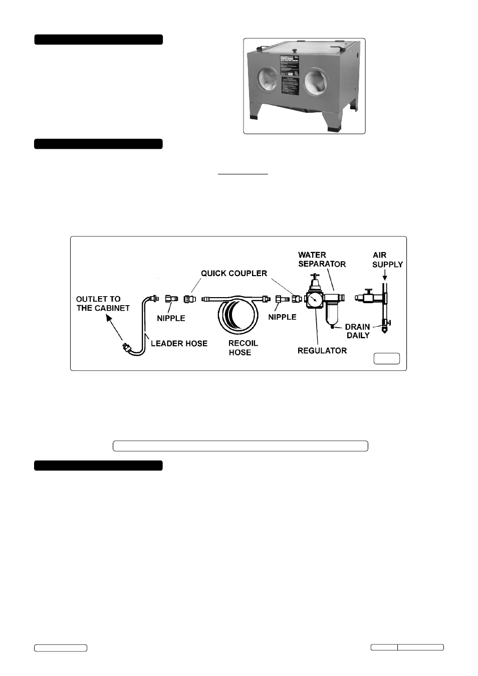
4.1. Air supply Fig.1
4.1.1. You will require an air pressure of 60-90psi, and an air volume of 12cfm to operate the unit efficiently.
4.1.2.
WARNING! Ensure air supply is clean, dry and does not exceed 90psi. Too high an air pressure and/or unclean or damp air will
shorten the product life due to excessive wear and may be dangerous, causing possible damage and/or personal injury.
4.1.3. Drain the air supply tank daily. Clean compressor air inlet filter weekly. For recommended hook-up see diagram below.
4.1.4. Line pressure should be increased to compensate for unusually long air hoses (over 8 metres).
The
minimum hose and fittings bore should be 10mm.
4.1.5. Keep hoses away from heat, oil and sharp edges. Check hoses for wear and poor connections.
4.1.6. Cabinet input connection is 1/4”BSP.
Recommended hook up diagram
Fig.1
© Jack Sealey Limited
3. SPECIFICATION
4. ASSEMBLY
5. OPERATION