Fig.1, Fig.2 fig.3, Assembly – Sealey PCB32 User Manual
Page 2
WARNING! Ensure that you have read and understood Section 1 Safety Instructions before operating the conduit
bender.
WARNING! When the conduit bender is packed in its box it is heavy and may require 2 people to move it.
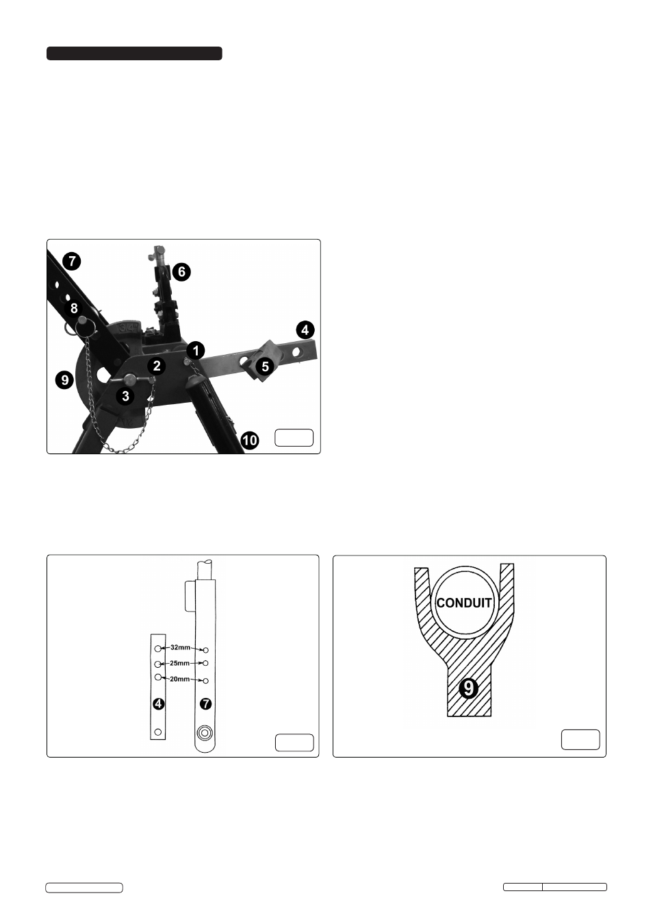
4.1. Remove the conduit bender from the box and check all parts are present. Refer to fig.1.
4.2. Remove the leg retaining pin (1) and open the conduit bender to its fullest extent. Re-insert the leg retaining pin (1) to lock the leg into
position.
4.3. The vice (6) is secured beneath the platform for transit purposes. Remove the 3 retaining bolts and remove the vice (6). Place it on
top of the platform and bolt into position.
4.4. Remove the bending lever retaining pin (2). Fit the former (9) and roller pin (8) in the appropriate position on the bending lever (7)
(fig.2). Secure the roller pin (8) in place with the R-clip.
4.5. Select the size of former (9) required (fig.2) according to the diameter of conduit to be bent. Withdraw the centre pin (3), insert the
former (9) and replace the centre pin (3).
4.6. Raise the bending lever (7) to the upright position and lock in place with the retaining pin (2). Attach the bending lever extension
(10).
4.7. Swing the stop bar (4) to the upright position and insert the stop piece (5) into the appropriate hole required and secure with the
R-clip. The conduit bender is now ready for use.
4. ASSEMBLY
PCB32.V2 Issue: 1 - 30/09/14
Original Language Version
© Jack Sealey Limited
fig.1
1.........................Leg retaining pin.
2.........Bending lever retaining pin.
3...................................Centre pin.
4......................................Stop bar.
5.................................. Stop piece.
6............................................ Vice.
7..............................Bending lever.
8.................................... Roller pin.
9........................................Former.
10...........Bending lever extension.
fig.2
fig.3