Fig.2 fig.3, Assembly 3. specification – Sealey TS10SEW User Manual
Page 3
4. ASSEMBLY
3. SPECiFiCATion
Motor . . . . . . . . . . . . . . . . . . . . . . . . . 1500W - 230V
speed . . . . . . . . . . . . . . . . . . . . . . . . . . . . . . 5700rpm
saw Blade diameter. . . . . . . . . . . . . . . . . . . Ø254mm
saw Blade Arbor. . . . . . . . . . . . . . . . . . . . . . . Ø20mm
Max. depth of 90° cut . . . . . . . . . . . . . . . . . . . 75mm
Max. depth of 45° cut . . . . . . . . . . . . . . . . . . . 60mm
Main table . . . . . . . . . . . . . . . . . . . . . . 440 x 625mm
side extension sizes (x2): . . . . . . . . . . 250 x 550mm
rear extension size: . . . . . . . . . . . . . . 320 x 435mm
table with extensions. . . . . . . . . . . . . . 940 x 945mm
dust extraction Port (taper). . . . . . . . . . . . . . Ø40mm
4.1.
the unit is best assembled upside down on a smooth and flat surface. ensure that the saw blade is fully retracted under the work
table before turning the unit over.
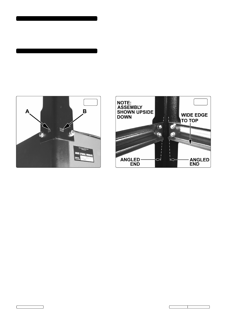
4.2.
Assemble a leg to each corner of the unit using two 12mm long bolts and two small washers. ensure that the two rectangular holes at
the top of each leg are aligned with the moulded rectangular spigots on each corner of the unit. see A & B in fig.2. do not fully tighten
the bolts at this stage.
4.3.
When all four legs are in place assemble the cross struts as shown in fig.3 using two 12mm long bolts, two nuts and two small
washers at each end of the strut. two of the struts are 20mm longer than the other pair and should be assembled to the legs above
the side of the unit that has the on/off switch and the opposite side above the dust extractor. each strut has a narrow returned edge
and a wide returned edge. the wide returned edge of each strut should always be nearest to the underside of the unit. note that the
ends of the cross struts are angled to match the outward angling of the legs. All fixings should be hand tight at this stage.
fig.2
fig.3
4.4.
using the four cheese headed screws provided attach each side table to the main table using two screws on each side.
4.5.
Identify the four shorter table stays and attach two to each side table. the two returned edges of the stays should be facing the
underside of the side tables. each stay shares one of the leg fixings at each corner. remove the leg fixing that lines up with the
appropriate fixing on the far edge of each side table and hold the stay in position whilst replacing the bolt. use a 12mm bolt, washer
and nut to fix the stay to the edge of the side table. repeat the process for all four stays.
4.6.
take the rear extension table and place it upside down on the floor at the back edge of the main work table. one side of the table has
slots which should be lined up with the threaded holes in the back of the main table and the other side has two holes for mounting the
stays. use two 12mm bolts to fix the extension to the main table. Attach the two longer stays to the rear extension table in the same
Original Language Version
ts10seW.V2 Issue: 1 - 11/07/13
way that the side stays were attached. now tighten all leg fixings, cross braces and stays.
4.7.
turn the assembly upright and check that the main table and extensions form a flat and step free surface.
4.8.
raise the blade and riving knife by turning the blade depth adjustment handle (fig.1.10) clockwise.
4.9.
remove the butterfly nut, bolt and washer from the blade guard and slide the guard over the riving knife until the hole in the knife
aligns with the hole in the guard. slide the bolt through both the knife and guard and replace the washer and butterfly nut.
4.10. take the mitre gauge and slide its metal bar into one of the slots on either side of the blade. Hold the mitre face extension bar in front
of the mitre gauge allowing the two sliding bolts at the back to drop into the slots in the mitre face. tighten the thumb wheels.
4.11. Attach the flexible dust extraction hose (fig.1.17) to the outlet on the blade guard (fig.1.9). Attach the other end to the dust extraction
inlet on the back of the saw.
4.12. lay the measurement scales provided, into the shallow recess on the upper face of the rip fence guide. fix in place with the 6 small
self tapping screws provided. do not fully tighten so that the measurement scale can slide within the bounds of the fixing slots.
4.13. take the rip fence (fig.1.5) and lift the locking handle to the horizontal position. Place the rip fence down over the rip fence guide
so that it rests flat against the left hand side of the saw blade and move the handle downwards to lock it in position. look through the
sight glass and adjust the position of the measurement scale so that zero is aligned with the sight glass mark. tighten the three fixing
screws that hold the left hand measurement scale. release the rip fence and place it flat against the right hand side of the blade.
repeat the alignment process for the right hand measurement scale and tighten the fixing screws. slide the rip fence away from the
blade.
© Jack sealey limited