Fig 9 fig 10, Fig 5 fig 6 fig 7 fig 8, Fig 11 fig 12 – Sealey SM900 User Manual
Page 4
4. HEAdSTOCK AdJUSTMENT
The headstock has five adjustment setting to provide flexibility of lathe use and are as follows:
1) 0° when the headstock is aligned with the bed and tailstock for spindle turning.
2) Angles of 60°, 90° and 120° to the bed for advanced faceplate turning.
3) A 180° turn for use with the extension bed and tool rest for outboard turning.
To set the headstock at the required angle proceed as follows:
4.1.
Loosen the head lock handle (fig 9.& 10.1) by one complete rotation.
4.2.
Pull out the headstock release knob (2).
4.3.
Rotate the entire headstock clockwise, let go of the release knob (2). The headstock will automatically fix itself in position when the
release knob clicks into one of the five preset positions. To change position pull the release knob again, and proceed until you lock the
head at the required angle.
WARNING!
1. Only undo the locking handle enough to allow the headstock to turn on the bed. dO NOT undo the lock so that the
head is unstable on the bed housing. The headstock is very heavy and may be dangerous if not turned and locked
correctly.
2. dO NOT turn headstock assembly more than 180° clockwise or anti-clockwise or the electrical wiring may be damaged
(fig 11).
fig 9
fig 10
3.4.
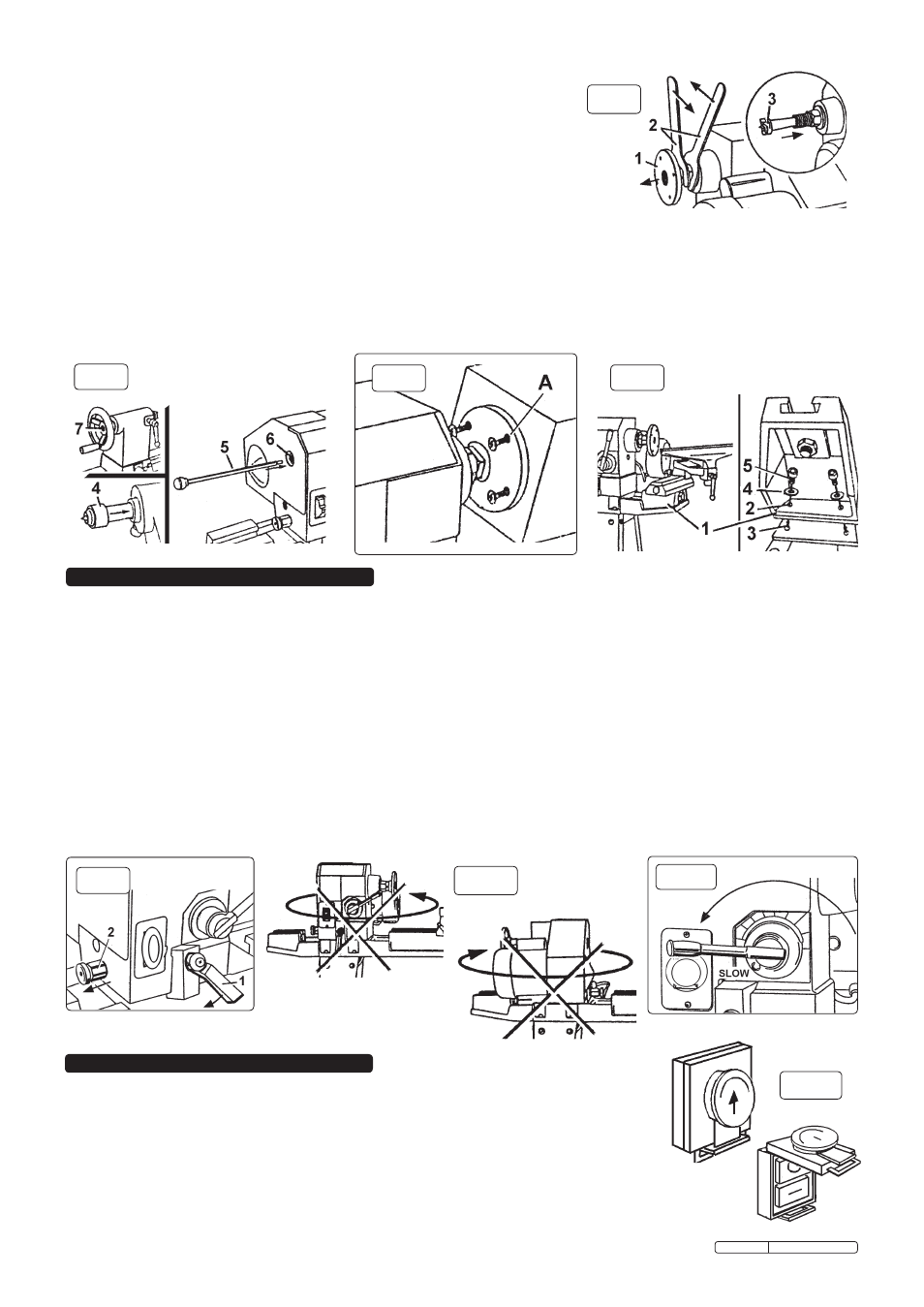
HEAdSTOCK SPUR (for between centre turning).
3.4.1. Remove faceplate (fig 5.1) from the headstock by using the two wrenches (2).
3.4.2. Insert the headstock spur (fig 5. 3) in the spindle hole.
3.4.3. Insert the tailstock centre (fig 6. 4) in the tailstock hole.
3.4.4. To remove headstock spur, insert push rod (fig 6. 5) into hole (6) at the rear of the
headstock
3.4.5. Remove tailstock by pushing rod (5) through the centre of the tailstock handle (7).
3.5.
FACEPLATE (Connecting workpiece for faceplate turning).
3.5.1. If assembled, remove the headstock spur from the spindle as above.
3.5.2. Thread the faceplate onto the headstock spindle.
3.5.3. Mount the workpiece to the faceplate with flat head, brass, wood screws. Ensure the length of
the screws will not interfere with the cutting tools (fig 7. A).
3.6.
EXTENSION bEd (for outboard faceplate turning).
The extension bed is attached to the rear of the headstock to accommodate the tool rest for outboard faceplate turning (fig 8).
3.6.1. If outboard faceplate turning does not require the use of the tool rest, do not attach the extension bed.
3.6.2. To attach the extension bed (fig 8.1) to the main bed, align the bolt holes (2) with the threaded bed holes (3). Put the lock washers (4)
on the hex bolt (5). Firstly finger tighten, then secure bolts with a hex key.
fig 5
fig 6
fig 7
fig 8
5. OPERATING INSTRUCTIONS
WARNING! dO NOT plug the lathe in to the electrical mains until you are ready for
turning. Ensure you read, understand and apply the safety instructions in chapter 1 before use.
5.1.
ON/OFF SWITCH
The speed control lever must be set on “sLOW”, before turning the lathe on as this will avoid
strain on the motor (fig 11). Generally, the speed may only be changed when the lathe is
operating. If the speed control is not set to “sLOW”, turn the lathe spindle manually, whilst gently
moving the speed control lever back to the “sLOW” indicator.
To access the ON/OFF switch lift the red tab up and lift the safety cover forward (fig 12).
Turn the lathe ON by depressing the “O” button, turn the lathe OFF by pressing the “I” button.
fig 11
fig 12
Original Language Version
sM900.V2 Issue: 2 - 25/03/10