Fig. 4 fig. 5 fig. 6, Fig. 3, Fig. 7 – Sealey SM1100 User Manual
Page 3: The on/off switch
3.4.
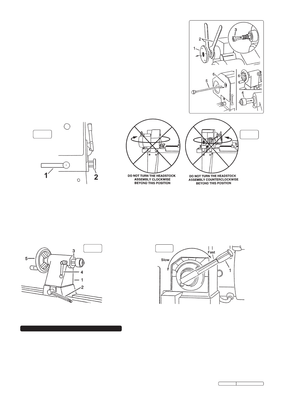
Centres (fig. 3)
3.4.1. Unscrew the face plate (1) from the headstock spindle using the two spanners (2)
provided.
3.4.2. Insert the headstock centre (3) into the spindle bore and tap gently into place with a soft
hammer or wooden block.
3.4.3. Similarly fit the tailstock centre (4) into the tailstock bore.
3.4.4. To remove either centre insert the push-out rod (5) into the bore (6) at the rear of the
headstock or tailstock, as appropriate. If necessary, gently tap the end of the rod with
a soft hammer.
3.5.
headstock (fig. 4)
The headstock may be rotated into any of five preset positions - 0° for spindle or face
plate turning and 60, 90,120 and 180° for face plate turning.
3.5.1. Loosen the head lock by turning the head lock handle (1) through 180°.
3.5.2. From the 0° position, pull out the headstock release knob (2) and rotate the headstock
clockwise to the required position.
Ensure that the spring loaded release knob has clicked into the locked position.
3.5.3. Reclamp the headstock by turning the head lock handle through 180°.
Warning! dO NOT turn the headstock by more than 180° from the spindle turning
position or wiring damage may occur. See fig. 5.
fig. 4
fig. 5
fig. 6
3.6.
Tailstock (fig. 6)
The tailstock may be moved along the lathe bed and the tailstock spindle adjusted by up to 2.5” (63mm) to suit the workpiece length.
3.6.1. Loosen the locking lever (2), reposition the tailstock (1) along the lathe bed and retighten the locking lever.
3.6.2. To move the tailstock spindle (3) loosen the spindle locking lever (4) and then turn the hand wheel (5) as necessary. Retighten the locking lever.
3.7.
Speed control (fig. 7)
Important! The motor must be running when the speed control lever is moved.
3.7.1. To change speed, pull back on the lever (1) and rotate it to the required setting.
Note that at each speed setting the lever, when released, will spring forward into the locked position.
3.7.2.
Before switching off the motor always select the slowest speed setting (lever fully anticlockwise) to ensure that the motor will restart easily.
fig. 3
Note: The lathe is fitted with a no-volt On/Off switch which automatically switches off if the supply is interrupted (power cut, socket
switched off etc.) thereby preventing unexpected, and therefore dangerous, start-up when the supply is reconnected.
4.1.
To switch the lathe on open the switch cover and press the “I” button. Allow the cover to close but do not press fully shut and latched
as this will switch off the lathe.
4.2.
To switch the lathe off normally open the switch cover and press the “O” button.
In an emergency push the red ‘button’ on the switch
cover. This will stop the lathe and also latch the switch cover closed, with the “O” button depressed. The lathe cannot be restarted until
the switch cover has been unlatched by sliding the red button upwards.
4. ThE ON/OFF SWITCh
fig. 7
Original Language Version
SM1100.V2 Issue: 3 - 23/03/10