Fig.5 fig.6 fig.7, Fig.9 fig.8 – Sealey AK2018 User Manual
Page 2
3.2
Wood Detection
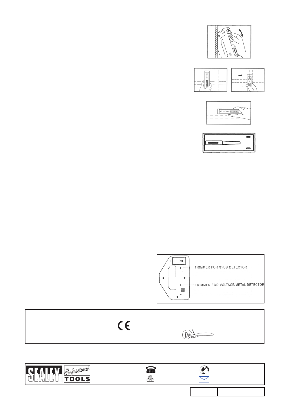
3.2.1 With the stud Detection face against the wall, hold the unit vertically as shown in
Fig.5 and turn knob A fully downwards.
3.2.2 Move the selector switch to the stud Detector position.
3.2.3 turn knob A upwards until the red LED and the buzzer come on.
3.2.4 reverse knob A gently until the green LED is just illuminated and the buzzer
ceases.
3.2.5 If the unit cannot be set, it needs to be adjusted. refer to section 3.4.
3.2.6 Move the unit horizontally across the wall. refer to Fig.6. Ensure that the
detector face marked ‘stuD’ is placed against the wall, otherwise the green LED
will go out and the calibration procedures will need to be repeated.
3.2.7 When the edge of a batten or wall stud is under the unit’s groove, the red LED
will come on and the buzzer will sound. Mark this position on the wall.
3.2.8 resume the movement of the unit. When the red LED and the buzzer go off,
leaving the green LED on, mark the position again. these marks indicate the
edges of the batten or wall stud. the mid-point between the two marks will be
the centre of the batten or wall stud.
3.2.9 to locate horizontal battens or studs, place the unit on the wall as shown in Fig.7
and use the method outlined above.
Notes: a) stud detection can be carried out normally on papered walls. However, it may
not function on some types of foil backed or metallic fabric surfaces.
b) If by chance the unit is placed over a wall batten or stud during calibration, the
green LED will go out and the buzzer cease to sound when the edge of the
batten, or wall stud, is under the unit groove.
c) A double width may be found around door and window frames due to double
battens or studs being encountered.
NOTE: It is our policy to continually improve products and as such we reserve the right to alter data, specifications and component parts without prior notice.
ImPORTaNT: no liability is accepted for incorrect use of this equipment.
WaRRaNTY: Guarantee is 12 months from purchase date, proof of which will be required for any claim.
INFORmaTION: For a copy of our latest catalogue and promotions call us on 01284 757525 and leave your full name and address, including postcode.
Fig.5
Fig.6
Fig.7
AK2018.V2
Issue no: 1 - 12/08/08
01284 757500
01284 703534
Sole uK Distributor
Sealey group,
Bury st. Edmunds, suffolk.
www.sealey.co.uk
Web
d) A solid wood header may exist in some doors or windows. the stud location will
not be found if the unit is calibrated on a normal wall first and then moved to the header area. It will indicate the
presence of a header.
e) It is advisable to take several readings along the batten or stud as nails may change the apparent centre position.
f) Frequent re-calibration can help to avoid false readings.
g) We recommend carrying out voltage/metal detection to make sure that the detected batten or stud is not a pipe or
cable. note that some small securing screws or nails may be detected.
3.3
maximising accuracy
the sensitivity of the unit can be used to pin-point the exact position of pipes, cables or battens and studs. to do
this, sweep the unit across the area in question, with the red light and buzzer sounding. After each sweep,
gradually adjust the knob, until the red light and buzzer are no longer activated. Gently reverse the knob before each
subsequent sweep, until the light and buzzer activate at the location of the pipe, cable, batten, or stud.
3.4.
unit adjustment
3.4.1 Metal/Voltage Detection Adjustment.
3.4.1.1 rotate the metal/voltage sensitivity knob B to mid-position.
3.4.1.2 slide the selector switch to the Voltage/Metal Detection position.
3.4.1.3 using the screwdriver, which is located under the battery cover, see Fig.8, turn the Metal/Voltage detection trimmer, refer
to Fig.9, as follows:
If the green LED is on, slowly turn the Metal/Voltage trimmer cLocKWIsE until the red LED and buzzer just come on.
slowly turn back the trimmer until the red LED just goes off and the buzzer ceases. the unit is now correctly adjusted.
3.4.2 stud Detection Adjustment.
3.4.2.1 rotate the knob A to mid-position.
3.4.2.2 slide the selector switch to the stud Detection position.
3.4.2.3 Hold the unit with stud face against the wall.
3.4.2.4 Adjust the trimmer, using the screwdriver, as follows:
If the green LED is on, slowly turn trimmer AntI-cLocKWIsE
until the red LED and buzzer just come on. slowly turn back
the trimmer until the red LED and the buzzer just turn off and
the green LED just turns on. the unit is now correctly adjusted.
Note: Switch off the detector when it is not in use by moving
the SElECTOR SWITCH to the mIDDlE POSITION.
Fig.9
Fig.8
Declaration of Conformity
We, the sole importer into the uK, declare that the products listed here are in conformity with the following
standards and directives.
3-IN-1 mETal, vOlTagE & STuD DETECTOR
model: aK2018.v2
93/68/EEc cE Marking Directive
2002/96/Ec WEEE Directive
the construction files for these products are held by the Manufacturer and may be
inspected, by a national authority, upon request to Jack sealey Ltd.
signed by Mark sweetman
For Jack Sealey Ltd. Sole importer into the UK of Sealey Power Products.
12th August 2008