Operation, Maintenance – Sealey RE83/840 User Manual
Page 2
Original Language Version
3. OPERATION
3.1
Setting up
3.1.1
Remove pipe plug from hydraulic adaptor and connect a hose (Model RE83/840.V2 only)
3.1.2
Remove the shipping plug from the air inlet port and insert a 1/4" NPT quick release coupler (If not fitted).
3.1.3
Connect an air supply to the quick release air hose coupler and connect the hydraulic hose to the ram or device coupler.
3.1.4
To operate the pump for ram/device extension/actuation, depress the treadle at the air inlet valve end.
3.1.5
To retract the ram/device to the original start position, depress treadle end marked "RELEASE". Retraction will stop with
load held, when pressure on treadle is removed. For fullest retraction continue to depress.
3.2
Operating requirements
3.2.1
For maximum performance and rated hydraulic pressure, air pressure should be 100psi minimum.
3.2.2
To ensure best performance the air supply equipment should include an air filter, regulator and lubricator. A minimum
requirement is an air filter with the air compressor tank drained of water every day and a small quantity of lubricating oil into
the air inlet each week.
3.2.3 Hydraulic output pressure can be controlled by regulating the air pressure. To determine the maximum hydraulic pressure
multiply the regulated air pressure reading by 100.
4.1
Release valve adjustment
4.1.1
Attach an air supply to the pump.
4.1.2 With an allen key loosen socket headed cap screw (Fig.2.) in treadle pivot boss two or three full turns.
4.1.3
With a screwdriver turn anti-clockwise the slotted head release valve (Fig.2. and Fig.3.) two full turns.
4.1.4
Lift the treadle at the air inlet end and depress the air valve button (Fig.1.) with your thumb.
4.1.5
Actuate the pump to build up pressure in the hose by depressing the treadle on to thumb and depressed air valve.
4.1.6
Using a screwdriver turn the slotted head release valve clockwise gently until resistance of the valve seat is felt. Excessive
tightening will cause loss of pressure in hose.
4.1.7
Continuing to depress the air valve button with your thumb to obtain operating clearance between the treadle air valve and
the release valve, tighten socket headed cap screw with an allen key through treadle pivot boss.
4.1.8
Release valve should now be correctly set.
NOTE: It is our policy to continually improve products and as such we reserve the right to alter data, specifications and component parts without prior notice.
IMPORTANT: No liability is accepted for incorrect use of this product.
WARRANTY: Guarantee is 12 months from purchase date, proof of which will be required for any claim.
INFORMATION: For a copy of our latest catalogue and promotions call us on 01284 757525 and leave your full name and address, including postcode.
01284 757500
01284 703534
Sole UK Distributor, Sealey Group,
Kempson Way, Suffolk Business Park
,
Bury St. Edmunds, Suffolk,
IP32 7AR
www.sealey.co.uk
Web
4. MAINTENANCE
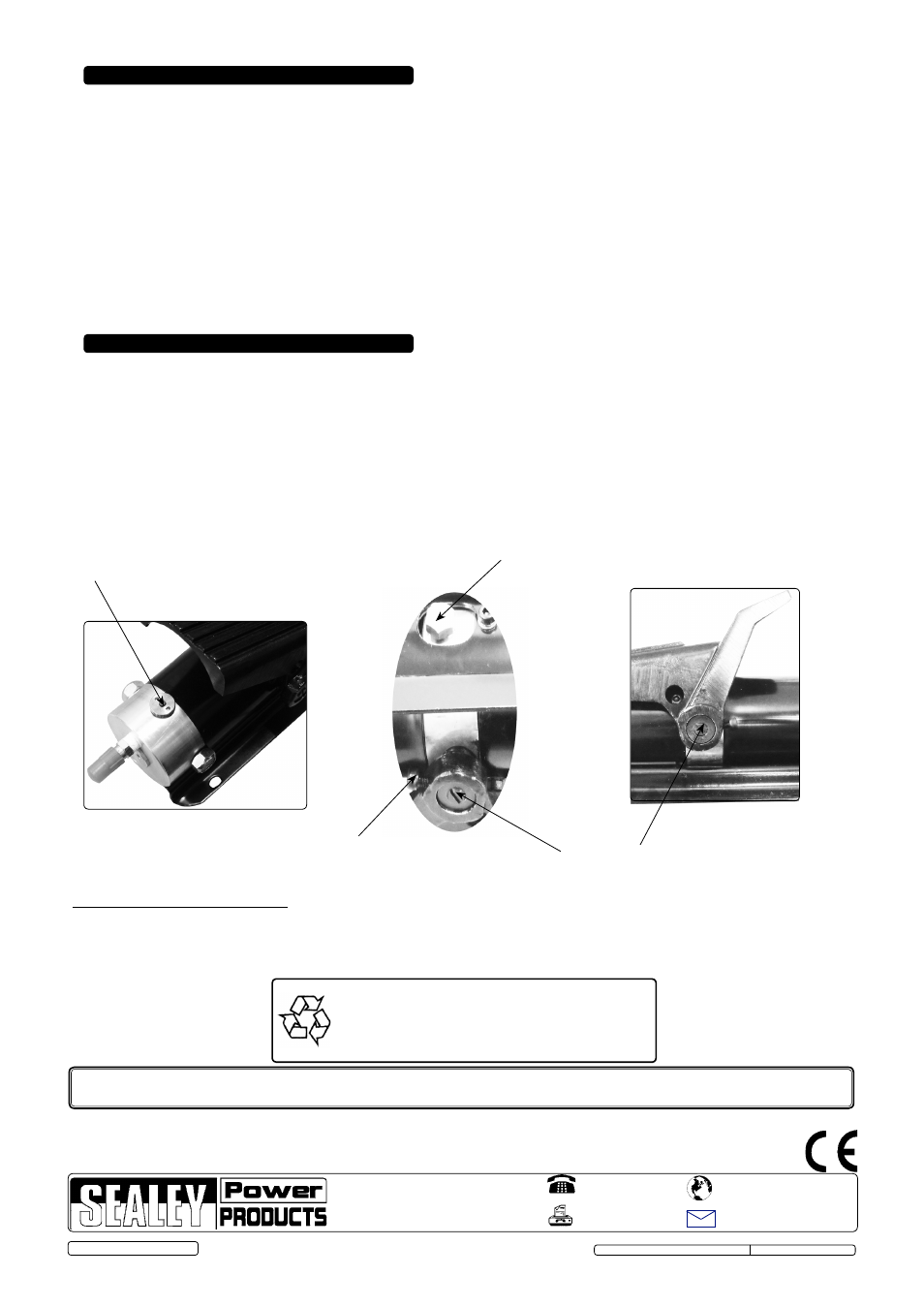
Fig.1.
Fig.2.
Oil filler plug (on underside)
Release valve
Air valve button
Socket head cap screw
Fig.3.
© Jack Sealey Limited 2013
Parts support is available for this product. To obtain a parts listing and/or diagram,
please log on to www.sealey.co.uk, email [email protected] or phone 01284 757500.
RE83/840.V2 & RE83/840/CWH.V2 Issue: 2(P) - 01/03/13
Environmental Protection.
Recycle unwanted materials instead of disposing of them as
waste. All tools, accessories and packaging should be sorted,
taken to a recycle centre and disposed of in a manner which
is compatible with the environment.
IMPORTANT: NO RESPONSIBILITY IS ACCEPTED FOR INCORRECT USE.
Hydraulic products are only repaired by local service agents. We have service/repair agents in all parts of the UK.
DO NOT RETURN PRODUCT TO US. Please telephone us on 01284 757500 to obtain the address and phone number of your local agent.
If product is under guarantee please contact your dealer.
De-commissioning Product
Should the product become completely unserviceable and require disposal, draw off the oil into an approved container and dispose of the
product and the oil according to local regulations.