Sealey MK59 User Manual
Panel stand, Mk59, Instructions for
INSTRUCTIONS FOR:
PANEL STAND
MOdel No:
MK59
Thank you for purchasing a Sealey product. Manufactured to a high standard this product will, if used according to these instructions
and properly maintained, give you years of trouble free performance.
IMPORTANT: PLEASE READ THESE INSTRUCTIONS CAREFULLY. NOTE THE SAFE OPERATIONAL REQUIREMENTS, WARNINGS AND CAUTIONS.
USE THE PRODUCT CORRECTLY AND WITH CARE FOR THE PURPOSE FOR WHICH IT IS INTENDED. FAILURE TO DO SO MAY CAUSE
DAMAGE AND/OR PERSONAL INJURY AND WILL INVALIDATE THE WARRANTY. PLEASE KEEP INSTRUCTIONS SAFE FOR FUTURE USE.
1. SAFETY INSTRUCTIONS
2. INTRODUCTION
3. ASSEMBLY INSTRUCTIONS
Familiarise yourself with the application and the limitations and
potential hazards of the stand.
Maintain the stand in good condition, use authorised replacement
parts only.
locate the stand in a suitable, clean work area.
WARNING! Use the stand on level and solid ground only, preferably
concrete.
DO NOT overload the stand.
DO NOT climb on the stand.
DO NOT use the stand for any purpose, other than that for which it
is designed.
DO NOT use the stand if any parts are damaged or missing as this
may cause failure and/or personal injury.
Keep the work area clean, uncluttered and ensure that there is
adequate lighting.
Keep children and unauthorised persons away from the work area.
Keep the stand clean for best and safest performance and when
not in use, store in a safe, dry, childproof location.
Suitable for supporting large panels from commercial vehicles.
Features fully adjustable arms to fit many styles of bonnets, wings,
doors, bumpers and tailgates. each level can rotate 360° as required.
Fitted with two fixed Ø180mm wheels and two braked Ø125mm
castors for easy manoeuvrability.
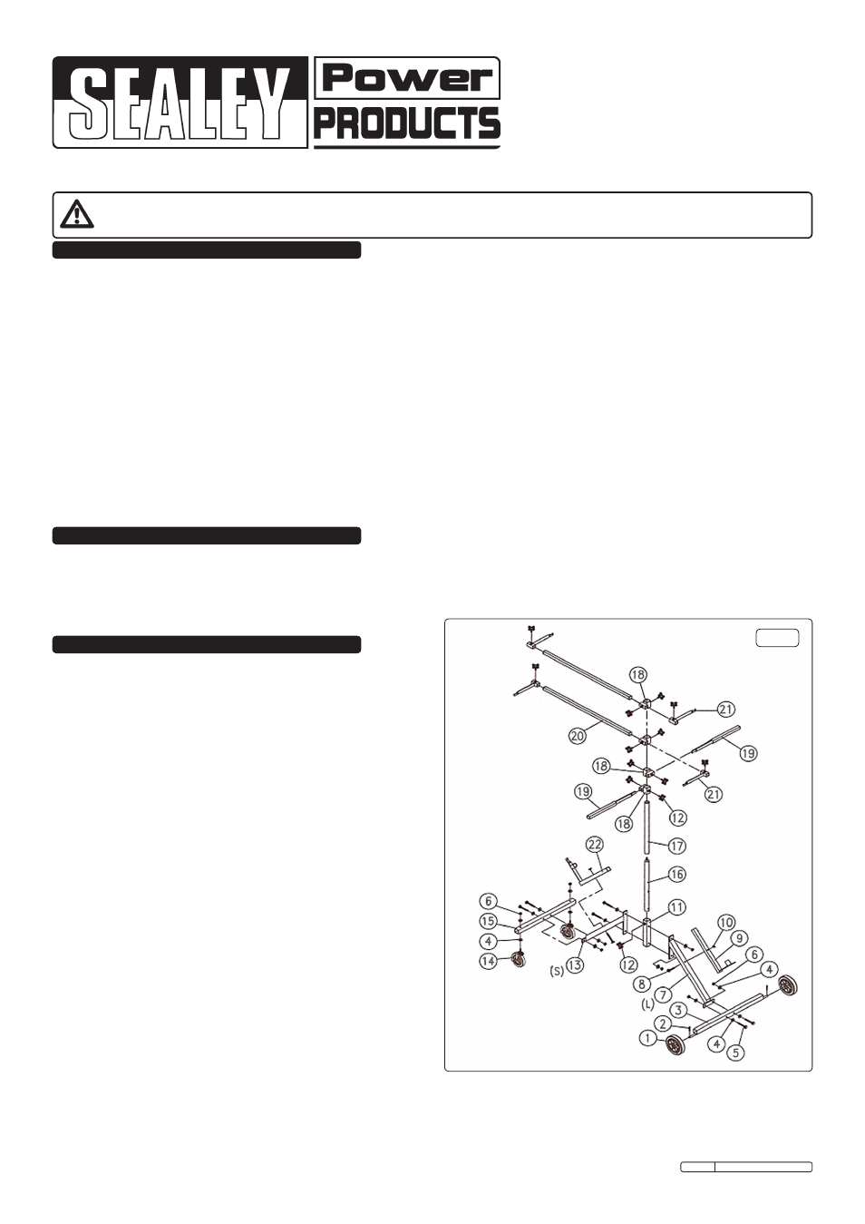
3.1. Check the contents against Fig.1 and the parts list to confirm
that all are present, and to familiarise yourself with the parts.
Refer to Fig.1. for assembly whilst following the steps below.
3.2. Mount the two oblique tubes (7 & 13) to the lower vertical tube
(11), fitting the middle vertical tube (16) inside the lower vertical
tube, align all holes, and use two bolts (5), four washers (4) and
two nuts (6) to secure.
3.3. Attach the long axle tube (3) to the long oblique tube (7) using two
bolts (5), four washers (4) and two nuts (6).
3.4. Attach the short axle tube (15) to the short oblique tube (13) using
two bolts (5), four washers (4) and two nuts (6).
3.5. Attach the swivel wheels (14) to the short axle tube (15) using four
washers (4) and two nuts (6).
3.6. Attach the wheels (1) to the long axle tube (3) by sliding them on
and retaining them using the two 'R' pins (2).
3.7. Attach the top vertical tube (17) to the middle vertical tube (16) by
screwing them together.
3.8. Attach the two brackets (9 & 22) to the oblique tubes, using two
bolts (8) and two wing nuts (10).
3.9. Slide the four adaptors (18) down over the top tube and secure in
place using the threaded fixing knobs (12).
3.10. Assemble the remaining cross tubes (20), and short and long
hooks (19 & 21) as per picture (fit in your desired positions). Also
see Fig.2 overleaf for final assembly.
MK59 Issue No:1 18/11/11
Part No. Description
Quantity
1
Wheel
2
2
'R' Pin
2
3
Axle Tube (long)
1
4
Washer
16
5
Bolt
6
6
Nut
8
7
Oblique Tube (long)
1
8
Bolt
2
9
Bracket (Right)
1
10
Wing Nut
2
11
lower Vertical Tube
1
12
Threaded Fixing Knob
13
13
Oblique Tube (Short)
1
14
Swivel Wheel
2
15
Axle Tube (Short)
1
16
Middle Vertical Tube
1
17
Top Vertical Tube
1
18
Adaptors
4
19
Hook (long)
2
20
Cross Tube
2
21
Hook (Short)
4
22
Bracket (left)
1
Fig.1
Original Language Version