Air supply, Operation, Fig. 2 fig. 1 – Sealey SM23/2 User Manual
Page 2
4. AIR SUPPLY
NOTE: The air supply for the SM23/2 must be equipped with a regulator, filter/separator and oiler in order to ensure safe operation and to
prolong the life of the product. These items are not supplied and must be purchased separately. Consult your local Sealey dealer for a suitable
product.
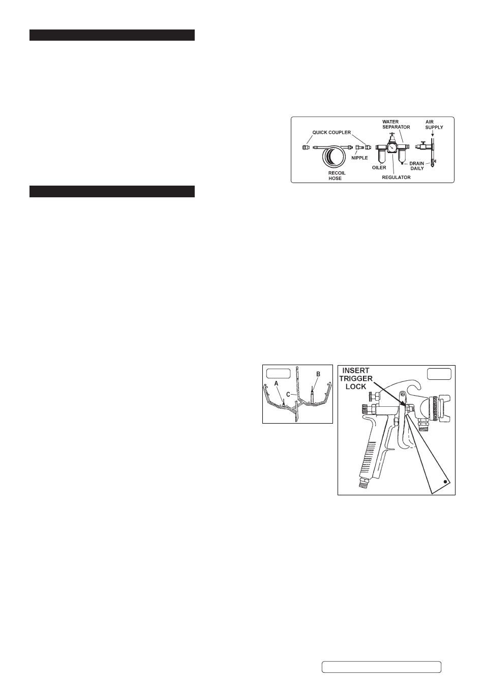
For recommended hook-up, see diagram below.
4.1.
Ensure that the air valve (20) is closed before connecting the air supply.
4.2.
An air pressure of 30-50psi, and an available air volume of 2-4cfm will be required to operate the unit.
R
WARNING! Ensure air supply is clean and does not exceed 50psi. Too high an air pressure and/or unclean air will shorten the
product life due to excessive wear, and may be dangerous, causing possible damage and personal injury.
4.3.
Drain the air supply tank daily. Water in the air line will damage the unit.
4.4.
Clean the air supply filter weekly.
4.5.
Line pressure should be increased to compensate for unusually long air
hoses (over 8 metres). The minimum hose internal diameter should be 10mm
and fittings must have the same internal dimension.
4.6.
Keep hose away from heat, oil and sharp edges. Check hoses for wear, and
make certain that all connections are secure.
4.7.
The air inlet connection is 1/4”BSP.
5. OPERATION
R
WARNING! Ensure you follow the safety instructions. Wear approved safety gloves, goggles, mask, and suitable clothing.
PREPARING TANK & ITEMS FOR CLEANING
5.1.
Water based paint. Ensure tank drain valve (66) is closed and then pour water into the tank (2). A suitable detergent (if required)
may be added. Refer to the detergent makers instructions for the correct amount of detergent to be added. Ensure that the final
water level is at least 1 inch (25mm) above the pump suction strainer (59).
5.2.
Confirm air valve (20) is closed and air supply pressure is regulated to not more than 50psi. Turn on air supply.
5.3.
Partially open air valve (20) and allow pump to run slowly for approx. 2 minutes to purge fluid used for manufacturer’s tests.
5.4.
Note: Lid (1) must be closed for pump to operate.
5.5.
Check the spray gun to be cleaned, empty and store any excess paint for future use. For best results clean immediately after use,
having removed as much residual paint as possible.
5.6.
To open the spray gun for cleaning, squeeze trigger and fit trigger lock (56) as shown in fig.1.
5.7.
Two gun supports are provided, one short (see fig.2A) and one long (see fig.2B). Use whichever support suits the configuration of
the gun to be cleaned. In general, guns which have top entry paint inlets (e.g gravity feed) can be put on either support provided
they do not foul on the underside of the lid. Guns which have bottom entry paint inlets (e.g suction feed) will usually go onto the
longer support.
5.8.
If required gun cleaning nozzle (8) may be fitted directly to manifold (6) without items (9) and (10) thus providing two short
nozzles.
5.9.
For pressure fed guns up to 2ltr capacity place the syphon stem of the pot cover over the short support and position the gun and
hoses on the screen platform. Over this capacity disconnect the gun from the lines and place on the long support.
5.10.
Place pots over nozzles ‘C’ (fig.2 - Screen (11) omitted for clarity).
CLEANING
5.11.
Ensure washer lid is closed and then open the pump air valve fully
(20).
5.12.
The pump will now operate and expel an atomized spray through
the nozzles in the cleaning tank.
5.13.
Cleaning will be complete after 45 seconds, at which time the pump
should be turned off by closing the air valve (20).
5.14.
Do not operate pump for longer than 2 minutes at any one time as this will reduce seal life.
5.15.
Open lid and remove cleaned equipment.
NOTE: If, during cleaning, the lid is opened, cleaning process will automatically stop.
Close the lid for cleaning to continue.
DO NOT store guns in tank.
fig. 2
fig. 1
SM23/2.V3 | Issue 3(S) 01/04/15
Original Language Version
© Jack Sealey Limited