Fig.1, Fig.2, Operating instructions 3. preparing tool for use – Sealey SA52 User Manual
Page 2
3.1. air supply
3 .1 .1 . Ensure tool valve (or trigger) is in the "off" position before connecting to the air supply .
3 .1 .2 . You will require an air pressure of 90psi, and an air flow according to specification .
3 .1 .3 .
WarninG! Ensure the air supply is clean and does not exceed 90psi while operating the
tool . Too high an air pressure and unclean air will shorten the product life due to excessive
wear, and may be dangerous causing damage and/or personal injury .
3 .1 .4 . Drain the air tank daily . Water in the air line will damage the tool .
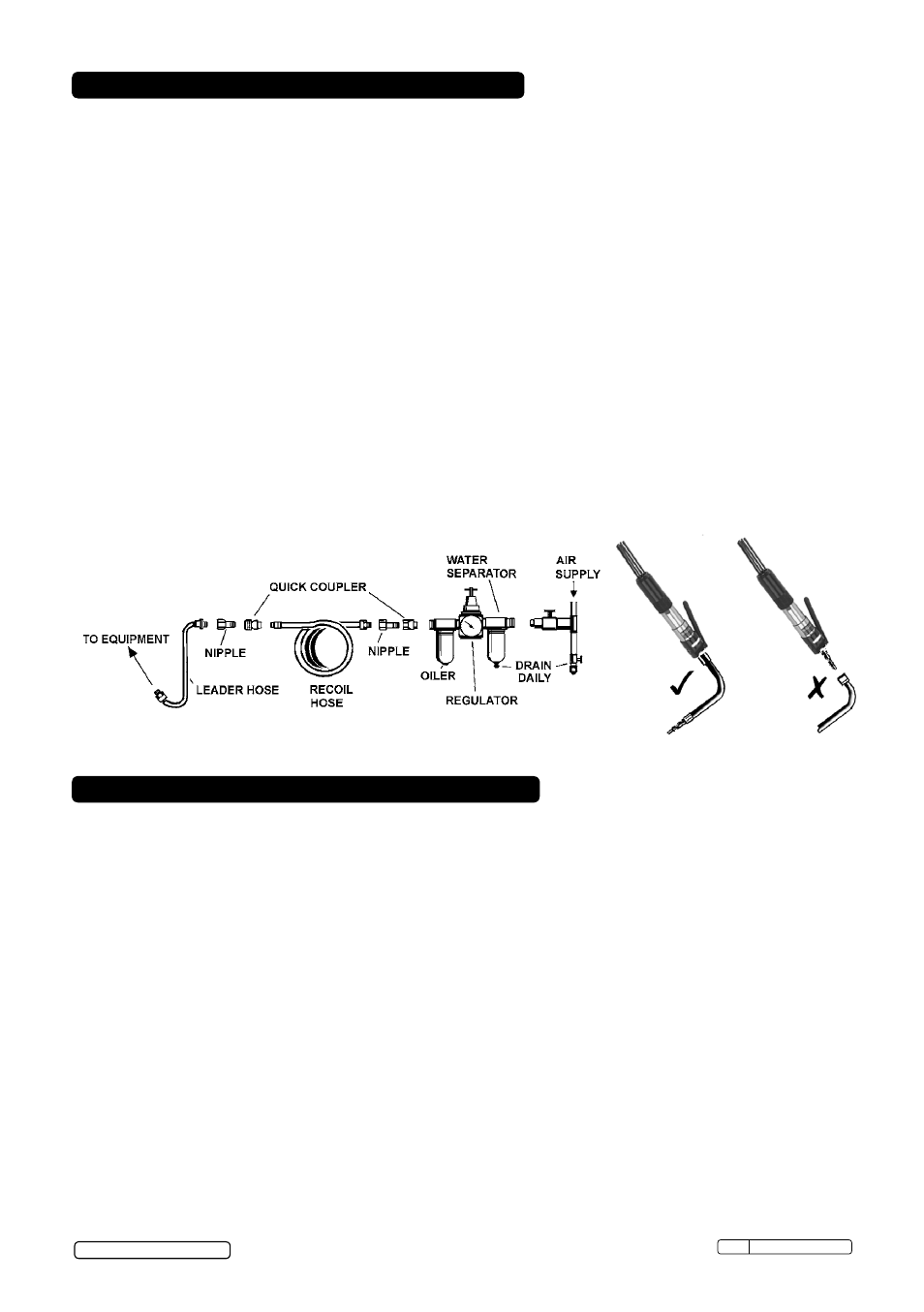
3 .1 .5 . Clean air inlet filter weekly . Recommended hook-up procedure is shown in fig .1 .
3 .1 .6 . Line pressure should be increased to compensate for unusually long air hoses (over 8
metres) . The minimum hose diameter should be 1/4” I .D . and fittings must have the same
inside dimensions .
3 .1 .7 . Keep hose away from heat, oil and sharp edges . Check hose for wear, and make certain
that all connections are secure .
3.2. couplings.
Vibration may cause failure if a quick change coupling is connected directly to the tool . To
overcome this, connect a leader hose to the tool . A quick change coupling may then be used
to connect the leader hose to the air line recoil hose . See fig .1 & 2 .
WarninG! ensure you read, understand and apply safety instructions before use.
note: Numbers in brackets refer to item numbers in the parts diagram .
4.1. flux chipper
4 .1 .1 . Fit the spring (4) onto the rounded end of the chisel (15) before fitting the chisel into the
barrel sleeve (12) .
4 .1 .2 . Fit the nut (20) over the sharpened end of the chisel (15), screw it onto the barrel sleeve
(12) and tighten .
4 .1 .3 . Connect the tool to the air hose as in chapter 3 .
4 .1 .4 . To start the tool, depress the throttle lever .
4.2. needle scaler
4 .2 .1 . To use as a needle scaler, unscrew the nut (20) and remove the chisel (15) and spring (4) .
4 .2 .2 . Fit the needle driver (14) and ensure the spring (18) is located in the needle tube (19) .
4 .2 .3 . Ensure the needle holder (17) is fitted with needles (16) such that the heads of the needles
do not protrude above the surface of the needle holder .
4 .2 .4 . Fit the needle holder (17) into the needle tube (19), screw the needle tube (19) onto the
barrel sleeve (12) and tighten .
4 .2 .5 . To start the tool, depress the throttle lever .
do not allow the tool to free run for an extended period of time as this will shorten its life .
fig.1
4. oPeratinG instructions
3.
PreParinG tooL for use
fig.2
Original Language Version
SA52 Issue: 3(SP) - 05/09/13
© Jack Sealey Limited