Fig.2 fig.1, Introduction & specification – Sealey SA44 User Manual
Page 2
2.
INTRODUCTION & SPECIFICATION
3.1
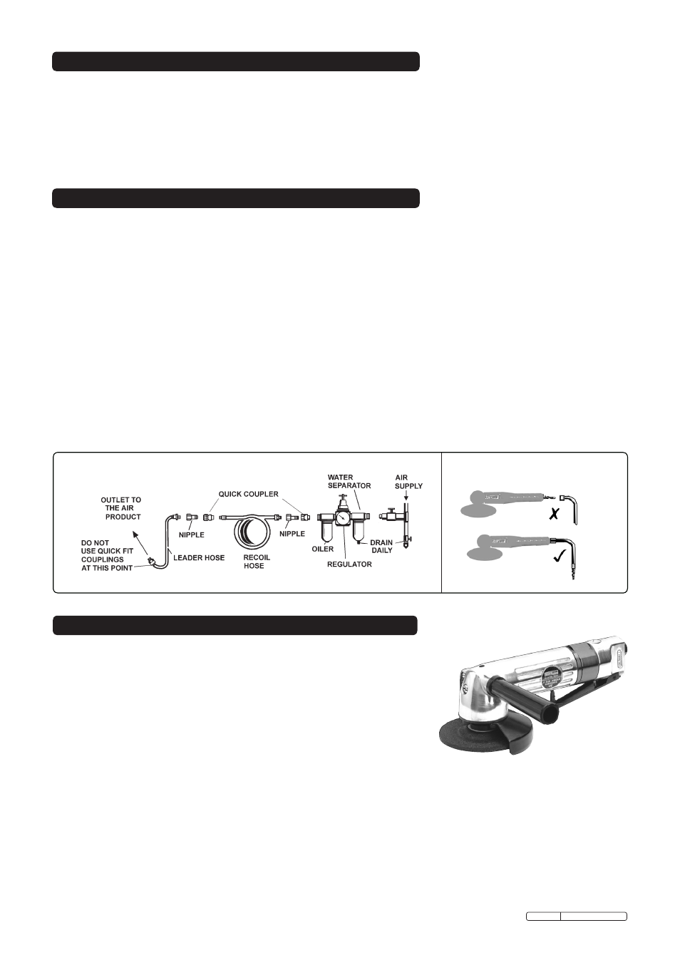
AIR SUPPLY
Recommended hook-up procedure is shown in fig.1.
3.1.1 Ensure the grinder air valve (or throttle) is in the "off" position before connecting to the air supply.
3.1.2 You will require an air pressure of 90psi, and an air flow according to the specification above.
3.1.3
WARNING! Ensure the air supply is clean and does not exceed 90psi while operating the grinder.
Too high an air pressure and unclean air will cause excessive wear, and may be dangerous, causing
damage and/or personal injury.
3.1.4 Drain the air tank daily. Water in the air line will damage the grinder and invalidate your warranty.
3.1.5 Clean air inlet filter weekly.
3.1.6 Line pressure should be increased to compensate for unusually long air hoses (over 8 metres).
The minimum hose diameter should be 1/4” I.D. and fittings must have the same inside dimensions.
3.1.7 Keep hose away from heat, oil and sharp edges. Check hoses for wear, and make certain that all
connections are secure.
3.2
COUPLINGS
Vibration may cause failure if a quick change coupling is connected directly to the air grinder. To overcome this,
connect a leader hose - Sealey model number AH2R or AH2R/38 - to the grinder. A quick change coupling may
then be used to connect the leader hose to the air line recoil hose. See figs. 1 & 2.
3.
PREPARING GRINDER FOR USE
4.
OPERATING INSTRUCTIONS
WARNING! Ensure you read, understand and apply safety
instructions before use.
4.1
ASSEMbLY
4.1.1 The SA44.V3 comes with a disc, handle and two spanners.
4.1.2 The handle screws into the left-hand side of the head.
4.1.3 Remove the disc locking flange nut from the grinder spindle.
Use spanners supplied to hold the spindle and loosen/tighten
the lock nut.
4.1.4 Fit the grinding disc to the spindle and retain with the flange nut.
Use only discs with speed ratings equal to, or higher than, the speed rating of the grinder.
4.1.5 Connect air supply to grinder. Push safety catch forward with thumb and squeeze the control valve lever
to check that the grinder is working correctly.
4.2
OPERATING
DO NOT apply excessive pressure, let the grinder do the work for you. Start the grinder and bring the
disc to the work surface evenly and slowly. Move the grinder back and forth in overlapping areas.
Remove the grinding disc from the work surface before stopping the grinder. Regularly check the
condition of the disc and always change if worn, cracked or otherwise damaged.
DO NOT allow grinder to run off the workpiece for an extended period of time as this will shorten the life
of bearings.
Disc Size . . . . . . . . . . . . . . . . . . . . . . 100mm
Free Speed . . . . . . . . . . . . . . . . . . 10000rpm
Operating Pressure . . . . . . . . . . . . . . . .90psi
Air Consumption . . . . . . . . . . . . . . . . . . 4cfm
Air Inlet . . . . . . . . . . . . . . . . . . . . . . 1/4”BSP
Sound Pressure . . . . . . . . . . . . . . . . 89dB(A)
Vibration . . . . . . . . . . . . . . . . . . . . . .2.33m/s2
Weight . . . . . . . . . . . . . . . . . . . . . . . . . .1.9kg
Aluminium body and bevel gear housing with steel disc guard and side handle. Fitted with throttle safety device
to prevent accidental operation. Balanced and comfortable to operate. Suitable for general/heavy workshop use.
Supplied with side handle, grinding disc and locking and pin spanners.
fig.2
fig.1
Original Language Version
SA44.V3 Issue: 3 - 08/12/09