Fig 1 fig 2 – Sealey GSA674 User Manual
Page 2
3.1.
Air Supply
Recommended hook-up procedure is shown in fig 1.
3.1.1. Ensure die grinder air valve (or trigger) is in "Off" position before connecting to the air
supply.
3.1.2. You will require an air pressure of 90psi, and an air flow according to specification.
3.1.3.
WARNING! Ensure the air supply is clean and does not exceed 90psi while operating the
die grinder. Too high an air pressure and unclean air will shorten the product life due to
excessive wear, and may be dangerous causing damage and/or personal injury.
3.1.4. Drain the air tank daily. Water in the air line will damage the die grinder.
3.1.5. Clean air inlet filter weekly.
3.1.6. Line pressure should be increased to compensate for unusually long air hoses (over 8
metres). The minimum hose diameter should be 1/4” I.D. and fittings must have the same
inside dimensions.
3.1.7. Keep hose away from heat, oil and sharp edges. Check hose for wear, and make certain
that all connections are secure.
3.2. Couplings.
Vibration may cause failure if a quick change coupling is connected directly to the die
grinder.
To overcome this, connect a leader hose to the grinder. A quick change coupling may then
be used to connect the leader hose to the air line recoil hose. See fig 1 & 2.
fig 1
fig 2
Model No. . . . . . . . . . . . . . GSA674.V2
Configuration: . . . . . . . . . . . . . 90°- Midi
Collet Size: . . . . . . . . . . . . . . . . . Ø6mm
Free Speed: . . . . . . . . . . . . . 20000rpm
Air Consumption: . . . . . . . . . . . . . .4cfm
Operating Pressure: . . . . . . . . . . . 90psi
Air Inlet Size: . . . . . . . . . . . . . .1/4”BSP
Weight: . . . . . . . . . . . . . . . . . . . . 0.54kg
Noise Power: . . . . . . . . . . . . . . .95dB.A
Noise Pressure: . . . . . . . . . . . . .84dB.A
Vibration (Load):. . . . . . . . . . . 1.44m/s²
Uncertainty: . . . . . . . . . . . . . . 0.72m/s²
4.1
FITTING Grinding Bit.
WARNING! Disconnect from the air supply before changing grinding bit.
4.1.1. Check that grinding bits are not damaged in any way such as cracks, deformations
or splinters etc Damaged bits must not be used.
4.1.2. Use spanners provided to loosen collet locking collar. Insert grinding bit and re-lock collar.
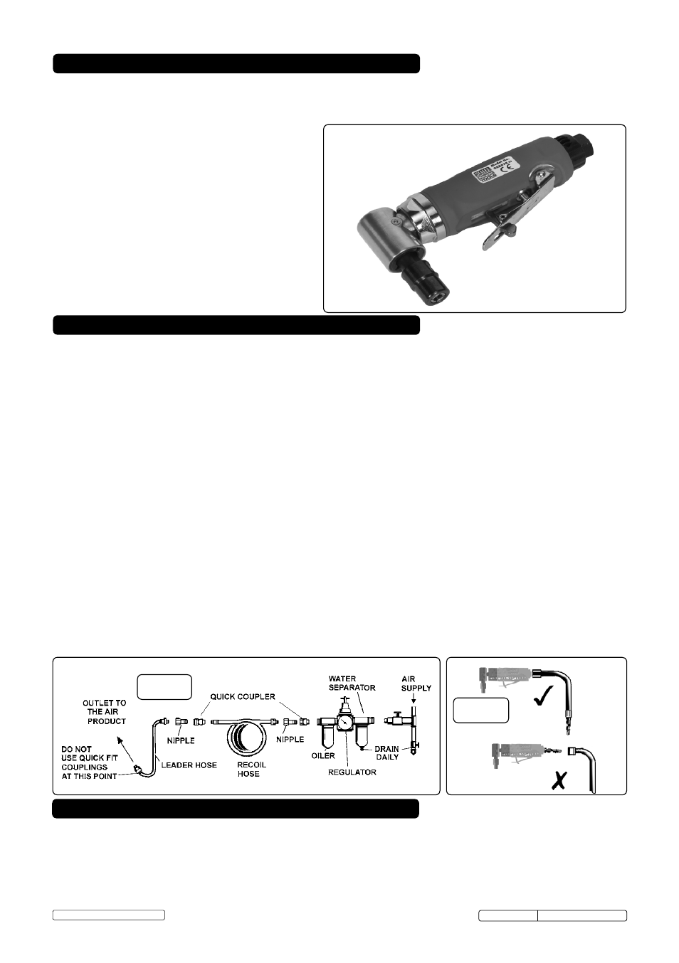
Contoured composite handle moulded around lightweight aluminium alloy housing reduces effects of chill on op-
erator’s hands and provides added control. Directional, low noise air exhaust can be rotated 360° giving operator
added protection. Fitted with safety trigger to prevent inadvertant operation. Supplied with adjustment spanners.
2. INTRODUCTION & SPECIFICATION
3. AIR SUPPLY
4. OPERATING INSTRUCTIONS
Original Language Version
GSA674.V2 Issue: 1 - 25/04/13
© Jack Sealey Limited