2 i/o network boards and peripherals, 1 the gateway board, 2 i/o n – Emerson E2 User Manual
Page 27: Etwork, Oards, Eripherals, 1 the gateway board -3
I/O Network Boards and Peripherals
Hardware Overview
•
2
-
3
2.1.5
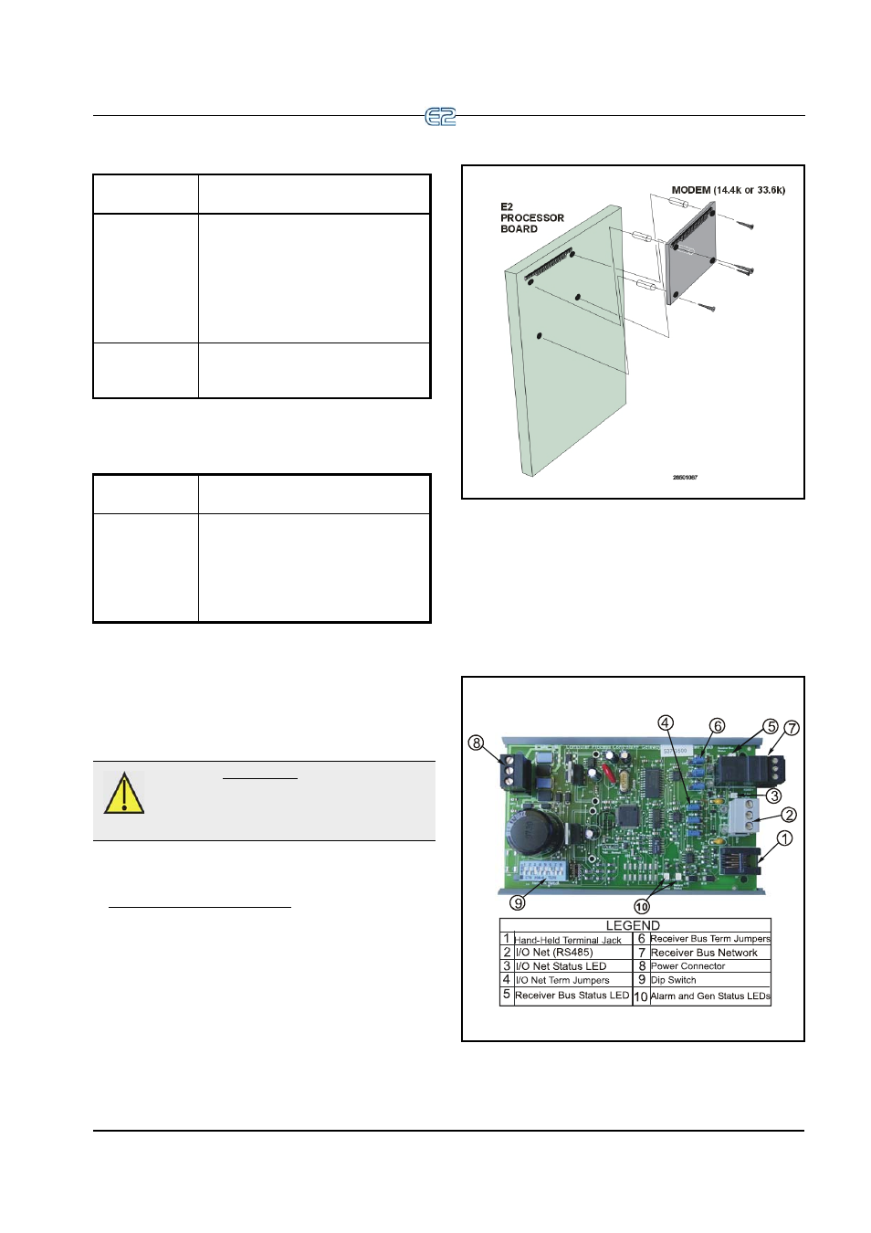
PC-104 Peripherals: The
Internal Modem (Previous Genera-
tion Processor Board)
The E2’s internal modem mounts in the PC-104 slot
located at the top left of the E2 main board (See Figure 2-
5). Disconnect power to the unit, and carefully plug the
male pins on the back of the modem card into the E2’s PC-
104 slot. Use the standoffs and screws supplied with the
modem card to secure the card to the main board, as
shown in Figure 2-5. When finished, restore power to the
E2.
2.2
I/O Network Boards
and Peripherals
2.2.1
The Gateway Board
Main Board
(CPU) LEDs
Status
Green (D1
General Sta-
tus LED for
E2 and Blank
Face E2)
1 blink every two seconds (1 sec-
ond ON, 1 second OFF): Main
board is operating normally.
Solid ON: E2 is booting up.
Faster blinks per second: Indi-
cates an error condition with the
hardware or firmware.
Green (D18
Boot Status
LED)
ON: E2 is booting up.
Table 2-3
- Main Board (CPU) LED’s Status
Keyboard
LED
Status
Green (D5
General Sta-
tus LED)
1 blink every two seconds (1 sec-
ond ON, 1 second OFF): Status is
normal.
4 blinks per second: A flash and/
or crystal problem has been de-
tected. Board should be replaced.
Table 2-4
- Keyboard LED’s Status
CAUTION: Power down the E2 before plug-
ging the modem into the PC-104 slot. Failure
to do so can damage the modem and void the
warranty.
Figure 2-5
- Mounting the Internal Modem Board
Figure 2-6
- Gateway Board