Intelligent pre-starts and pre-stops, 11 separate setpoints, 12 ahu zone control – Emerson E2 User Manual
Page 166: 13 hardware overview
11-24
•
E2 RX/BX/CX I&O Manual
comfortably within the range of the new setpoint.
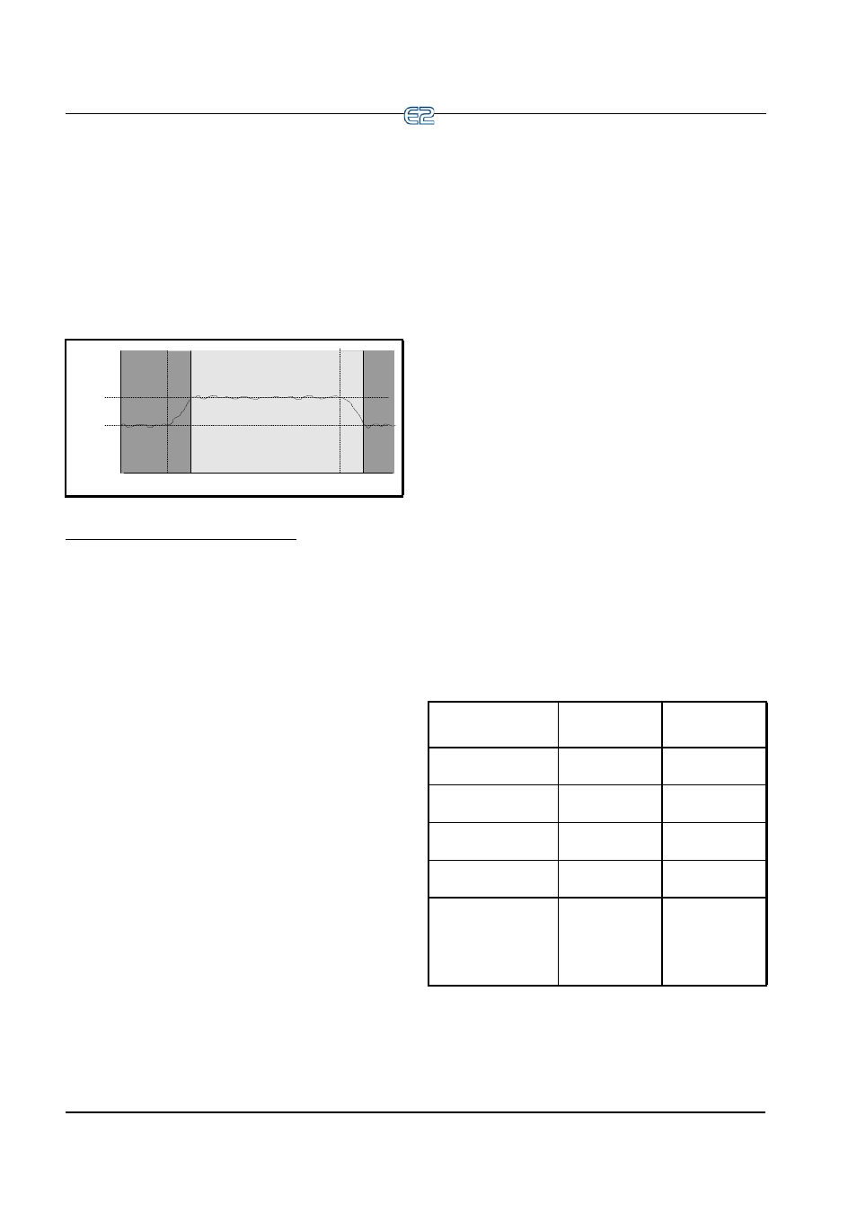
Figure 11-15 shows an example of how pre-starts and
pre-stops work in a heating application. From unoccupied
mode, the pre-start period ramps the temperature up
slowly so that when the scheduled change from unoccu-
pied to occupied mode occurs, the temperature will
already be at or near the occupied heating setpoint. During
the pre-stop, which occurs before AHU Control goes from
occupied to unoccupied mode, heating is suspended and
the temperature is allowed to “coast” down to the unoccu-
pied setpoint.
Intelligent Pre-Starts and Pre-Stops
OSS is designed to handle pre-starts and pre-stops in
the most energy-efficient manner possible. Every time a
pre-start or pre-stop occurs, OSS measures the amount of
time it takes to bring the temperature from the previous
setpoint to within the “comfort zone” of the new setpoint
(a user-defined range of values above and below the set-
point within which the temperature is considered accept-
able). This duration is used to determine the average rate
of temperature change, called the K factor.
The K factor is stored in the memory along with the
average value of the outdoor air temperature during the
pre-start or pre-stop. Over time, collected K factor data
will be sorted and combined into a table. As a result, by
constantly observing and recording the results of previous
pre-starts and pre-stops, OSS will be able to intelligently
guess how much time a pre-start or pre-stop mode should
last based on the outside temperature.
AHU Control keeps track of three different kinds of K
factors:
• Heat K factor - used to guess pre-start dura-
tions for AHUs operating in heating mode.
• Cool K factor - used to guess pre-start dura-
tions for AHUs operating in cooling mode.
• Coast K factor - a measurement of the
change in temperature when no heating or
cooling is active. This is used to determine
pre-stop durations for both heating and cool-
ing AHUs.
11.6.11 Separate Setpoints
The Separate Setpoints strategy for AHU allows a Cut
In/Cut Out setpoint to be set up for each heat and cool
stage instead of just one cool and one heat setpoint set up
for each stage (Normal strategy). Dehumidification con-
trol can be performed while controlling with separate set-
points.
11.6.12 AHU Zone Control
Unlike MultiFlex RTU rooftop controller applications,
AHU applications are not required to be grouped into
Zone applications (AHUs are usually large enough to be
“zones” in and of themselves).
However, if desired, you may associate an AHU Con-
trol application with a Zone application. The AHU will
then use the Zone’s Temperature Control setpoints, occu-
pancy state, summer/winter state, and economization and
dehumidification enable signals. More information on
Zone control is available in Section 11.7, Zone Control.
11.6.13 Hardware Overview
To set up an AHU for control by an E2, numerous tem-
perature and humidity sensors for several different appli-
cations must be connected to the I/O Network, as well as
fan and cool proof checking devices, economization
checking devices, curtailment devices, and all of the heat-
ing, cooling, and dehumidification outputs.
Listed below are wiring instructions for some of the
inputs and outputs that are part of a typical AHU setup.
Figure 11-15
- Diagram of Pre-Start and Pre-Stop Operation
OCCUPIED
SET POINT
UNOCCUPIED
SET POINT
UNOC
C
U
PIED
UNOC
C
U
PIED
PRE-ST
ART
OCC
U
PIED
PRE-ST
OP
(COAST)
26512036
Inputs
Sensor Type
Wiring
Instructions
Space Temperature
Temperature
Space Humidity
Humidity
Supply Air Temp
Temperature
Return Air Temp
Temperature
Outdoor Air Temp
Temperature
Set up as Out-
door Air Provider
in Global Data
(see
).
Table 11-10
- Suction Group Inputs