2 condenser control, 1 air cooled condensers, 1 air cooled strategy – Emerson E2 User Manual
Page 145: 2 temperature differential strategy, Ondenser, Ontrol, 1 air cooled condensers -3, Figure 11-1, In table 11-1 and table 11-2, 2 temperature differential strat- egy
Condenser Control
Software Overview
•
11
-
3
11.2 Condenser Control
An E2 RX is capable of controlling air-cooled or evap-
orative condensers. The E2 RX-300 may control a single
condenser, while the RX-400 may control up to two con-
densers.
11.2.1 Air Cooled Condensers
An air-cooled condenser consists of one or more fans
that blow air across a manifold of tubing to cool heated
refrigerant and condense it into a liquid. The E2 controls
condensers by activating or deactivating fans in order to
maintain discharge pressure or temperature at or below a
chosen setpoint.
A Condenser Control application may use either of two
strategies to operate air cooled condensers: an air-cooled
strategy, or a temperature differential (T-D) strategy.
11.2.1.1 Air Cooled Strategy
The air cooled strategy uses a simple PID control loop
that compares a single Control In input to a PID setpoint.
The resulting percentage is used to activate the condenser
fan(s) necessary to bring the input value down below the
setpoint.
Control inputs for air cooled strategies most commonly
come from a pressure transducer mounted on either the
discharge line, the condenser inlet, or the condenser outlet.
However, temperature sensor values will also be accepted.
11.2.1.2 Temperature Differential Strat-
egy
The temperature differential strategy attempts to keep
a minimum amount of difference between the temperature
of the refrigerant and the ambient outside temperature.
This strategy begins by determining the temperature of
the refrigerant coming into the condenser. This can be sup-
plied by either a temperature sensor or pressure transducer
located near the condenser inlet; if it’s a pressure trans-
ducer, its value will automatically be converted to a tem-
perature value based upon the type of refrigerant.
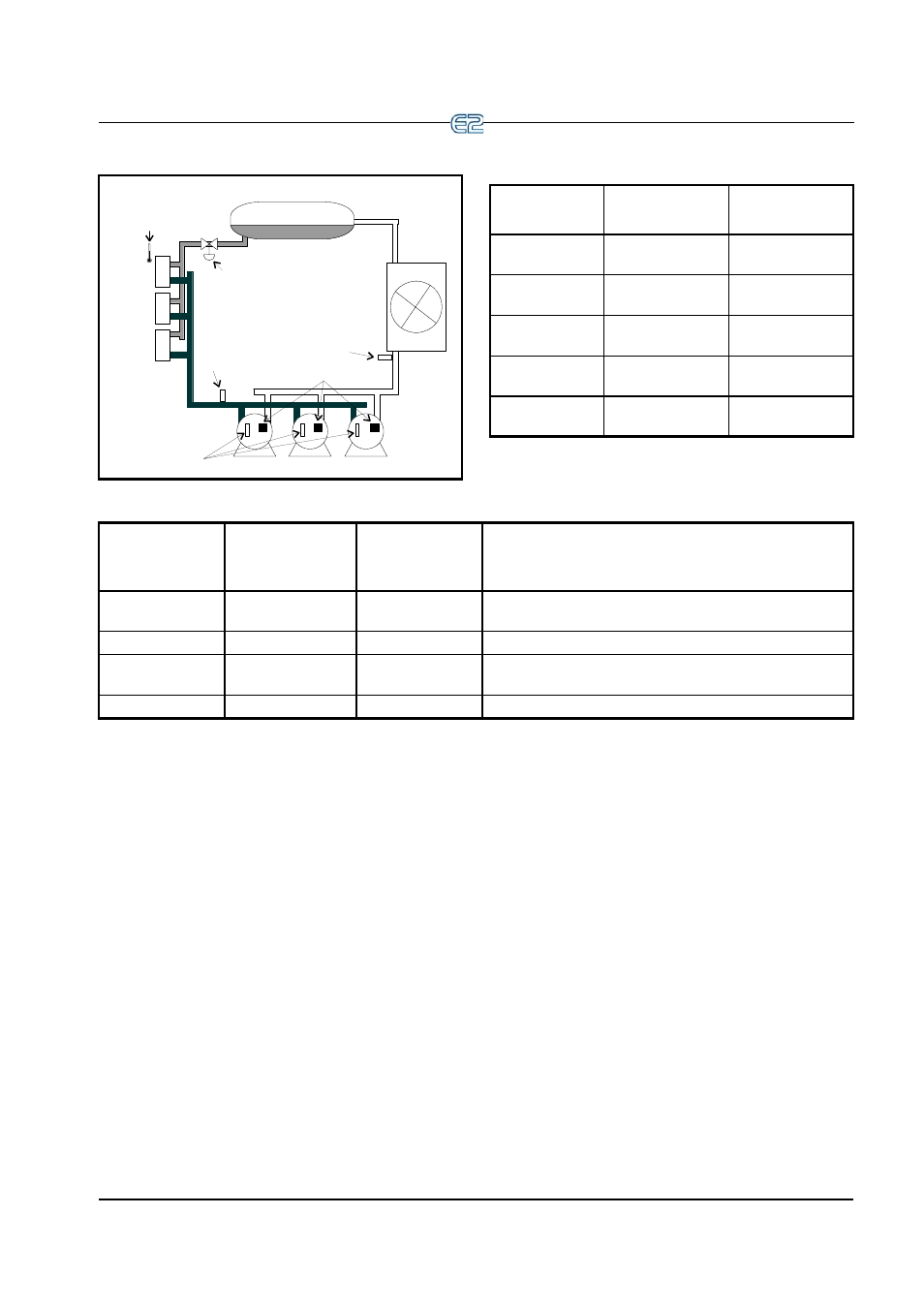
Figure 11-1
- Diagram of a Suction Group
SUCTION
PRESSURE
CO
NDEN
S
E
R
DISCHARGE
PRESSURE
LIQUID RECEIVER
CASE CIRC
UIT
OIL
PRESSURE
CIRCUIT
CASE TEMP
(FOR FLOATING)
LIQUID LINE
SOLENOID
26507005
D
D
D
OIL RESET SWITCHES
Input
Sensor Type
Wiring
Instructions
Suction Pressure
100 lb. Eclipse
transducer
Discharge Pres-
sure
500 lb. Eclipse
transducer
Oil Pressure
200 lb. Eclipse
transducer
Case Circuit
Temperature
Temperature
Oil Reset
Switches
Digital
Table 11-1
- Suction Group Inputs
Output Device
Wire Output
Board Contacts
to:
Set Failsafe Dip
Switch to:
Notes
Compressor
N.C.
N.C. (up)
If you want a compressor to be OFF during network/power loss,
use N.O. failsafes instead.
Unloader
N.C.
N.O. (down)
These fail-safe settings are specifically for unloaders.
Liquid Line Sole-
noid (LLS)
N.C.
N.C. (up)
Keeps solenoid energized during network/power loss.
Electric Defrost
N.O.
N.O. (down)
Keeps contacts de-energized during network/power loss.
Table 11-2
- Suction Group Outputs