Appendix c, Installing the optional display, Appendix c installing the optional display – Emerson IFT9701 User Manual
Page 81: Warning
HA
R
T
Me
n
u
T
re
e
s
Retu
rn
P
o
li
c
y
Op
tio
n
al Di
sp
la
y
Spec
ifications
Model IFT9701 Transmitter Instruction Manual
73
Appendix C
Installing the Optional Display
To install the optional display, follow these steps:
1. Make sure you are wearing an anti-static wrist strap.
2. Disconnect input power to the flowmeter.
3. Loosen the captive screws that hold the field wiring compartment cover in place, then remove
the cover.
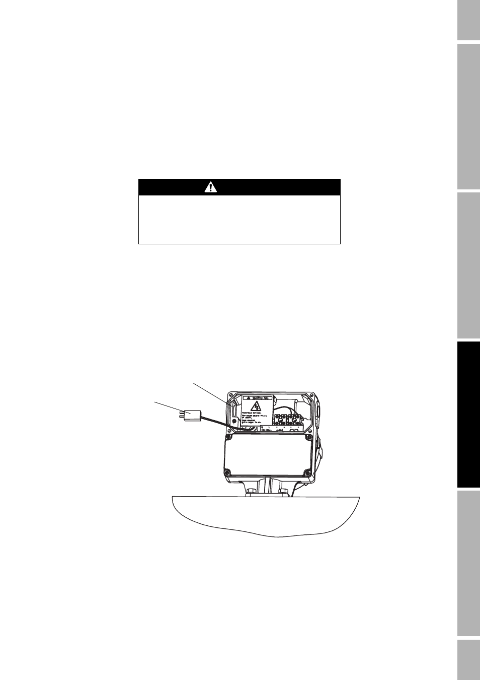
4. A pair of wires and a connector, which connect to the display, are tucked behind the label for
the power supply wiring terminals in the field wiring compartment. Carefully move the wire
pair and connector from behind the label, as shown in the illustration below.
5. On the back of the display is a spring-loaded retaining clip, which is held in place by a screw
and washer. Because the retaining clip springs open, exercise care to avoid losing the screw
and washer as they are removed. Remove the screw and washer.
6. Plug the male connector that is attached to the back of the display into the female connector
that is attached to the wire pair.
7. Slip the retaining clip over the wire pair.
WARNING
Line voltage can cause electric shock or transmitter
damage.
Disconnect input power before installing display.
Connector
Field wiring
compartment