Remotely mounting the transmitter continued, Terminal number wire color function – Emerson IFT9701 User Manual
Page 25
Model IFT9701 Transmitter Instruction Manual
17
Remotely Mounting the Transmitter
continued
Ge
tti
n
g
Sta
rted
P
o
w
er
Su
pp
ly
an
d O
u
tp
ut Wi
ri
ng
Mounting the
Remo
te T
ransmitter
Be
fo
re
Y
o
u
Begin
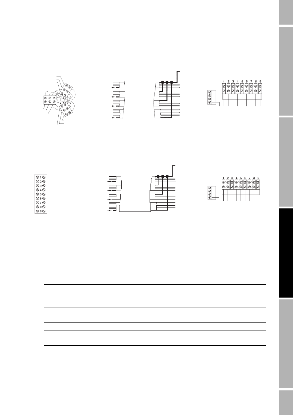
Figure 3-7
Cable connections to sensors
Table 3-3
Sensor terminal designations
Terminal number
Wire color
Function
1
Brown
Drive +
2
Red
Drive –
3
Orange
Temperature –
4
Yellow
Temperature lead length compensator
5
Green
Left pickoff +
6
Blue
Right pickoff +
7
Violet
Temperature +
8
Gray
Right pickoff –
9
White
Left pickoff –
10
11
12
GND
Green
White
Brown
Violet
Yellow
Orange
Blue
Gray
Red
Brown
Red
Clip drain wire back
Green
White
Clip drain wire back
Blue
Gray
Clip drain wire back
Orange
Violet
Yellow
Clip drain wire back
ELITE
and F-Series
sensor terminals
Flowmeter
cable
IFT9701
terminals
Brown
Red
Green
White
Blue
Gray
Orange
Violet
Yellow
Black
(Drains from all
wire sets)
Maximum cable length 1000 ft. (330 m)
Prepare cable in accordance with the
instructions that are shipped with the cable
Blac
k (Dr
a
in
s
,
re
mo
te-m
ou
nt o
n
ly)
Br
o
w
n
Re
d
Or
an
ge
Y
e
llo
w
Gre
e
n
Blu
e
V
iol
et
Gr
a
y
Wh
it
e
10
11
12
GND
Brown
Red
Orange
Yellow
Green
Blue
Violet
Gray
White
Brown
Red
Clip drain wire back
Green
White
Clip drain wire back
Blue
Gray
Clip drain wire back
Orange
Violet
Yellow
Clip drain wire back
Flowmeter
cable
IFT9701
terminals
Brown
Red
Green
White
Blue
Gray
Orange
Violet
Yellow
Black
(Drains from all
wire sets)
Maximum cable length 1000 ft. (300 m)
Prepare cable in accordance with the
instructions that are shipped with the cable
Blac
k (
D
ra
ins
,
rem
o
te
-mo
un
t o
n
ly)
Br
o
w
n
Red
Oran
ge
Ye
llo
w
Gree
n
Blu
e
V
iol
et
Gr
a
y
Wh
it
e
*Model D600 and DT sensors cannot be used
with IFT9701 transmitters
D and DL
sensor terminals*