2 flow calibration procedure, Flow calibration procedure – Emerson IFT9701 User Manual
Page 61
Model IFT9701 Transmitter Instruction Manual
53
Configuration with ProLink II Software
continued
Co
nfig
uratio
n wit
h
Co
mm
u
n
ic
ato
r
T
ro
u
b
lesho
ot
ing
Con
fig
ur
atio
n
w
ith
Pr
oL
in
k
II
Flo
w
meter Star
tup
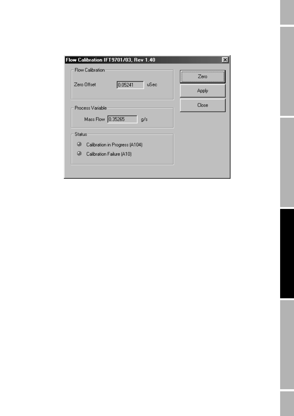
Figure 7-5
Flow Calibration dialog box
Diagnosing zeroing failure
If zeroing fails:
•
The Calibration Failure status light turns red.
•
The meter’s diagnostic LED blinks ON four times per second.
•
The flowmeter produces fault outputs.
•
The message “ELEC0” blinks on and off in the meter’s optional display.
The most common sources of zeroing failure are:
•
Flow of fluid through meter during zeroing
•
Partially empty flow tubes
•
An improperly mounted meter
Re-zero the flowmeter after correcting the problem, or cycle power to the meter to abort the entire
zeroing procedure and return to the previously established zero.
7.3.2
Flow calibration procedure
Flow calibration involves adjusting the flow calibration factor so it accurately represents the
sensitivity of the flowmeter to mass flow. Performing the flow calibration procedure in the field is
optional.
Flow calibration is performed by running a batch of fluid through the meter, weighing the fluid, then
using the Totalizer Control window to compare the weighed amount with the amount of fluid
measured by the flowmeter. The accuracy of the scale used for weighing the fluid will determine the
accuracy of the flow calibration. Use a scale that is highly accurate.