E table 3-1, See table 3-2 for guidelines on – Emerson IFT9701 User Manual
Page 23
Model IFT9701 Transmitter Instruction Manual
15
Remotely Mounting the Transmitter
continued
Ge
tti
n
g
Sta
rted
P
o
w
er
Su
pp
ly
an
d O
u
tp
ut Wi
ri
ng
Mounting the
Remo
te T
ransmitter
Be
fo
re
Y
o
u
Begin
Figure 3-5
Shielded cable
Jacket
material
Outside
diameter
Minimum bend radii
Static
(no load)
condition
Under
dynamic
load
inches (mm)
inches (mm)
inches (mm)
PVC
0.525 (14)
4 1/4 (108)
8 1/2 (216)
Teflon
®
FEP
0.425 (11)
3 1/4 (83)
6 3/8 (162)
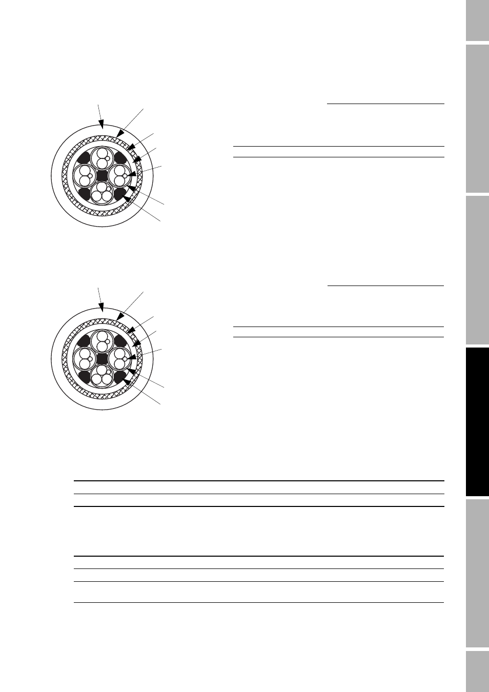
Figure 3-6
Armored cable
Jacket
material
Outside
diameter
Minimum bend radii
Static
(no load)
condition
Under
dynamic
load
inches (mm)
inches (mm)
inches (mm)
PVC
0.525 (14)
4 1/4 (108)
8 1/2 (216)
Teflon
®
FEP
0.425 (11)
3 1/4 (83)
6 3/8 (162)
Table 3-1
Temperature ranges for jacket material
Jacket material
Low operating temperature limit
High operating temperature limit
PVC
–40 °F (–40 °C)
221 °F (105 °C)
Teflon
®
FEP
–76 °F (–60 °C)
302 °F (150 °C)
Table 3-2
Cable selection guidelines
Installation requirements
Jacketed cable
Shielded cable
Armored cable
Conduit is used
Conduit is not used
Conduit is not used and
mechanical protection is required
Outer jacket
Tin-plated copper
braided shield
Foil shield (1)
Inner jacket
Drain wire (4)
Filler (5)
Foil shield (4)
Outer jacket
Stainless steel
braided shield
Foil shield (1)
Inner jacket
Drain wire (4)
Filler (5)
Foil shield (4)