4 pulse output, Pulse output, See section 4.4.4 – Emerson IFT9701 User Manual
Page 33: To section 4.4.4 to, Caution
Model IFT9701 Transmitter Instruction Manual
25
Power Supply and Output Wiring
continued
Ge
tti
n
g
Sta
rted
P
o
wer
Su
pp
ly
an
d O
u
tp
ut Wi
ri
ng
Mounting the
Remo
te T
ransmitter
Be
fo
re
Y
o
u
Begin
4.4.4
Pulse output
The pulse output is a passive, open collector interface that can be connected to a pulse counter such as
the Micro Motion Series 3000 applications platform. The output has a range of 0.1 to 7200 Hz, which
represents the mass or volume flow rate. At the factory, the output is scaled so that the frequency is
proportional to the range of flow rates measured in the application.
•
The pulse output is galvanically isolated to ±500 VDC from the rest of the flowmeter.
•
When connected to the Series 3000 applications platform, the pulse output does not require an
external power source. Otherwise, the pulse output requires a 5–30 VDC power source.
•
In the ON state, voltage will be less than 1 V.
•
For wiring to any pulse counter, see Figures 4-6 and 4-7.
•
For wiring to the Series 3000 applications platform, see Figures 4-8 through 4-10.
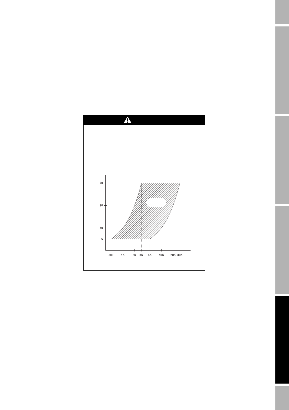
CAUTION
Exceeding specified current limit through the pulse
output circuit will damage the flowmeter.
Make sure the current through the pulse output circuit
does not exceed 10 mA.
For acceptable resistance values at on and off states of
the pulse output, see illustration below.
Acceptable
resistance
V
o
ltag
e (V
o
lts)
Resistance (Ohms)