Epson Stylus TX100 User Manual
Page 70
Epson STYLUS NX100/NX105/SX100/SX105/TX100/TX101/TX102/TX103/TX105/TX106/TX109/ME 300
Revision A
DISASSEMBLY/ASSEMBLY
Disassembling the Printer Mechanism
70
Confidential
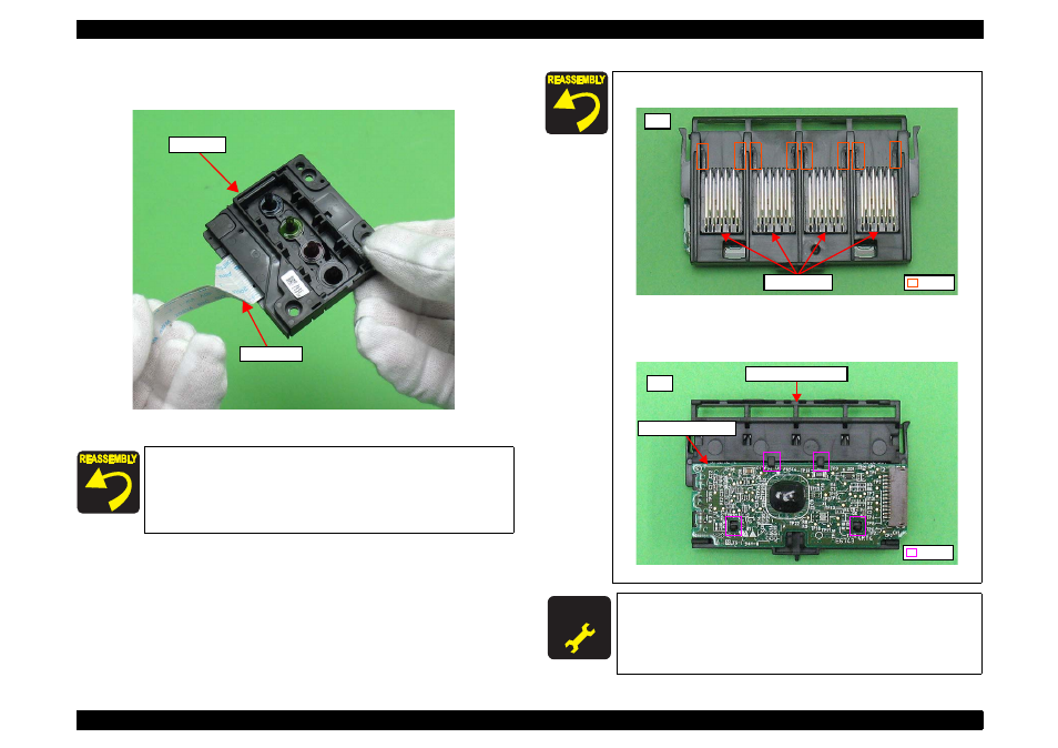
7. Remove the Head FFC from the connector of the Printhead, and remove the
Printhead.
Figure 4-32. Removing the Printhead (7)
When installing the FFC, route it through objects as shown in
.
When installing the FFC Cover, insert its rib to the hole of the
CR Unit and secure it with the hook. (See
.)
Printhead
Head FFC
When installing the Contact Assys, secure them to the Holder
Contact Assy with two each hooks on the Contact Assys.
Figure 4-33. Assembling the Holder Contact Assy (1)
When installing the CR Contact Module, secure it with four
hooks of the Holder Contact Assy.
Figure 4-34. Assembling the Holder Contact Assy (2)
A D J U S T M E N T
R E Q U I R E D
Whenever the Printhead is removed/replaced, the required
adjustments must be carried out.
•
Chapter 5 “ ADJUSTMENT” (p.100)
Front
Contact Assys
Hook
Back
CR Contact Module
Holder Contact Assy
Hook