Warning – Emerson Liebert NX 50 and 60 Hz User Manual
Page 97
Operating Procedures
85
7. Press the EPO (Emergency Power Off) button at the UPS front panel of this UPS module only.
This will disable further Rectifier, Inverter, Static Switch and Battery operation. This will not
affect the manual maintenance bypass power switch.
8. Open the Rectifier input power switch Q1 and Static bypass input power switch Q2
9. When an external battery is connected, open external battery circuit breaker. This breaker is
located inside the battery cabinet (if used) or is otherwise adjacent to the battery racks
All mimic panel LED indications and messages will extinguish as the mains driven internal
power supplies decay.
The load is now powered from the maintenance bypass supply and the UPS is completely
shut down.
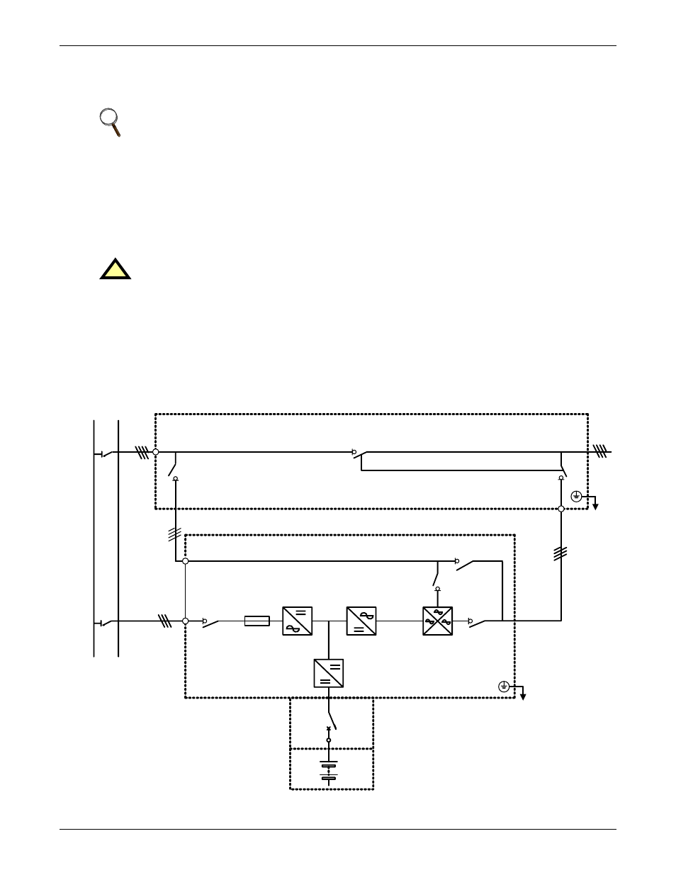
Figure 65 Example of configuration for single UPS with external Maintenance Bypass Cabinet
NOTE
Do not press any remote EPO button.
!
WARNING
Hazardous Voltage at UPS terminals
No operator-serviceable parts are located behind covers that require a tool for their removal.
Only qualified service personnel are authorised to remove such covers.
The input and output AC and DC battery and connecting terminals remains energized at
hazardous voltage levels at all times. The battery is located behind protective covers that
require a tool for their removal. inside the UPS cabinet (30 and 40kVA models), inside a free-
standing battery cabinet or on open racks inside a dedicated battery room that may be locked.
Q1
UPS
Supplied
by Others
CB
U5/V5/W5/N5
U3/V3/W3/N3
U1/V1/W1/N1
U4/V4/W4/N4
U2/V2/W2/N2
U6/V6/W6/N6
Q3
Q5
Q2
QF2
QF4
QF3
External Maintenance Bypass Cabinet