Warning – Emerson Liebert NX 50 and 60 Hz User Manual
Page 94
Operating Procedures
82
In multi-module systems—perform each step of the procedure in every UPS module before proceed-
ing to the next step.
1. Open the UPS door to gain access to the main power switches.
2. Close Bypass input power switch Q2 and UPS output power switch Q5.
Close also any external output isolation switches, where used.
The LCD becomes active and after initialization, the UPS output is powered from the bypass,
with the bypass and load indicators turned on.
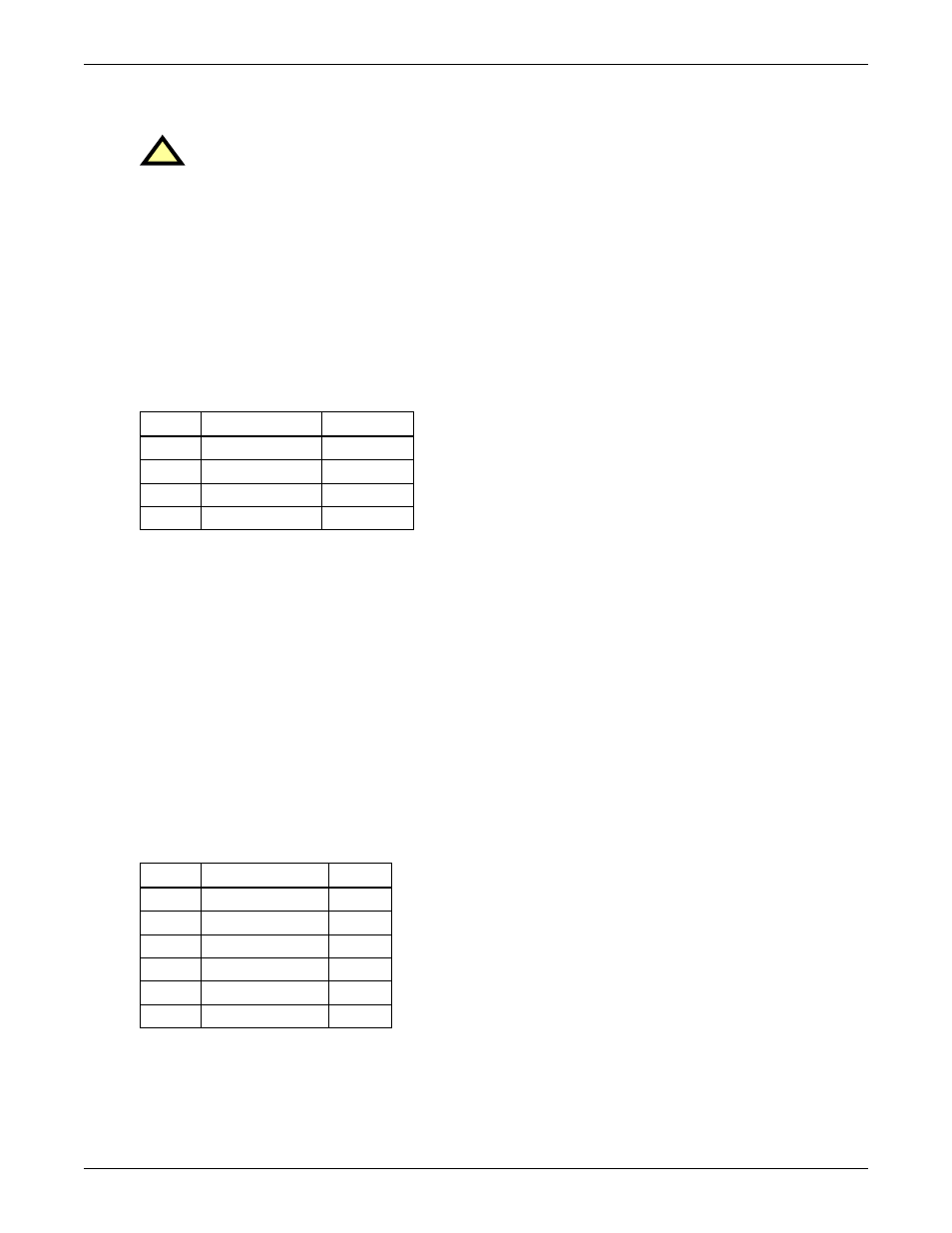
The UPS Mimic LED's will indicate (refer to Figure 67):
3. Close the Rectifier AC Input Power Switch Q1.
The Rectifier indicator flashes on the UPS mimic panel during the startup of rectifier and
becomes steady green once the rectifier reaches normal operation state after about 30s.
4. Close external battery circuit breaker (where an external battery is used). This breaker is located
inside the battery cabinet (if used) or is otherwise adjacent to the battery racks
5. Following battery availability being detected by the UPS, the red battery indicator extinguishes
moments after when the battery charger starts operation.
6. Open (or confirm open) the internal Manual Bypass Power Switch Q3.
Open also any external Maintenance Bypass Switch, where used.
7. Press INVERTER ON button for two seconds.
The inverter will start up and the inverter indicator flashes while it synchronises to the bypass
voltage frequency.
After the inverter is ready, the UPS transfers from bypass to inverter, the bypass indicator turns
off, and the inverter indicator becomes steady green.
8. Check that no “Warning” message is displayed in the top right corner of the LCD Monitor and the
status of the indicators are:
The UPS is now operating in NORMAL mode.
!
WARNING
Mains Voltage will be applied to UPS output terminals.
This procedure results in mains voltage being applied to the UPS output terminals.
• Isolate and attach warning labels to any downstream load connections, as applicable.
• No operator serviceable parts are located behind covers that require a tool for removal.
• Only qualified service personnel are authorised to remove such covers.
# LED
LED Function
Status
3
Bypass indicator
Green
5
Output indicator
Green
2
Battery indicator
Red
6
Alarm indicator
Amber / red
# LED
LED Function
Status
1
Rectifier indicator
Green
2
Battery indicator
Off
3
Bypass indicator
Off
4
Inverter indicator
Green
5
Output indicator
Green
6
Alarm indicator
Off