Installation, 2 installation procedure – Magnum Energy Battery Monitor Kit ME-BMK User Manual
Page 9
5
© 2010 Magnum Energy, Inc.
Installation
2.2 Installation Procedure
Select a location that is dry and away from extreme temperatures to mount the
ME-BMK Sense Module and DC shunt. Use the supplied #8 x 3/4 screws (x4).
Allow ample room to view the LED on the Sense Module, access the screws
and bolts on the shunt, and to access the terminal block and the RJ11 port.
CAUTION: Do not mount the ME-BMK Sense Module in a closed
battery compartment, or in an area
where water
or any other liquid
can enter the ME-BMK Sense Module and cause shorting or corro-
sion. The internal circuit board is conformal coated to help prevent
corrosion, but this failure is not covered by the warranty.
Info: Shunts should be mounted in an area where freely circulating
air is available. For continuous operation, it is recommended that
shunts are not used at more than 2/3 of their rated current. If this
is not possible, adequate forced ventilation should be provided to
keep the shunt operating temperature below 60°C.
CAUTION: Before beginning the installation, ensure all AC power is
disconnected from the inverter, and all negative
and positive battery
cables are disconnected from the battery bank.
2.2.1 DC Cable Connections
1. Using an appropriate sized cable, wire the inverter’s DC negative terminal
to the DC shunt (load side).
Info: For the ME-BMK to monitor all load currents, all DC loads — includ-
ing the inverter — must be connected to the load side of the shunt.
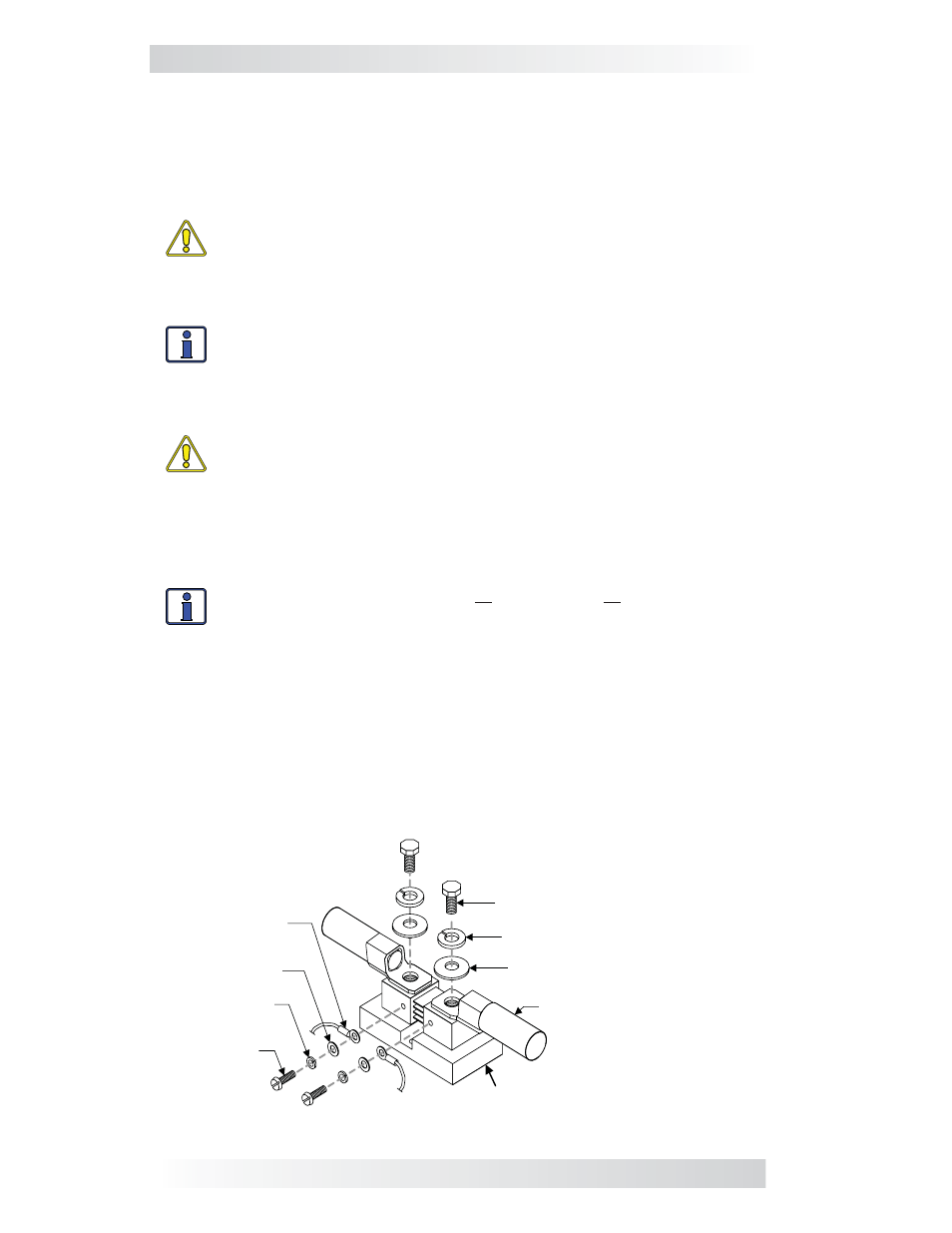
2. Wire the other side of the DC shunt (battery side) to the battery negative ter-
minal. Connect
cables/hardware to the shunt exactly as shown in
Figure 2-2.
3. Using an appropriate sized cable, wire the inverter’s DC positive terminal
to the load side of an appropriate DC disconnect/overcurrent protection device
(i.e., DC circuit breaker, or DC disconnect and fuse).
4. Open the DC circuit breaker (or remove the fuse) and wire its other side
to the positive terminal of the battery bank.
Cable (x2) – one side to
inverter, other to battery
(use ring lug w/ 3/8" opening)
Flat washer (x2)
Split-lock washer (x2)
3/8"-16 bolt with 9/16" head (x2)
8-32 x 3/8"
screw (x2)
Flat washer (x2)
Sense wire with
ring terminal to
Sense Module (x2)
Split-lock
washer (x2)
DC Shunt
Figure 2-2, DC Shunt Connections