Using led indicator to determine bmk’s status, Led status meaning – Magnum Energy Battery Monitor Kit ME-BMK User Manual
Page 34
© 2010 Magnum Energy, Inc.
30
Using LED Indicator to Determine BMK’s Status
6.0 Using the LED Indicator to Determine the
BMK’s Status
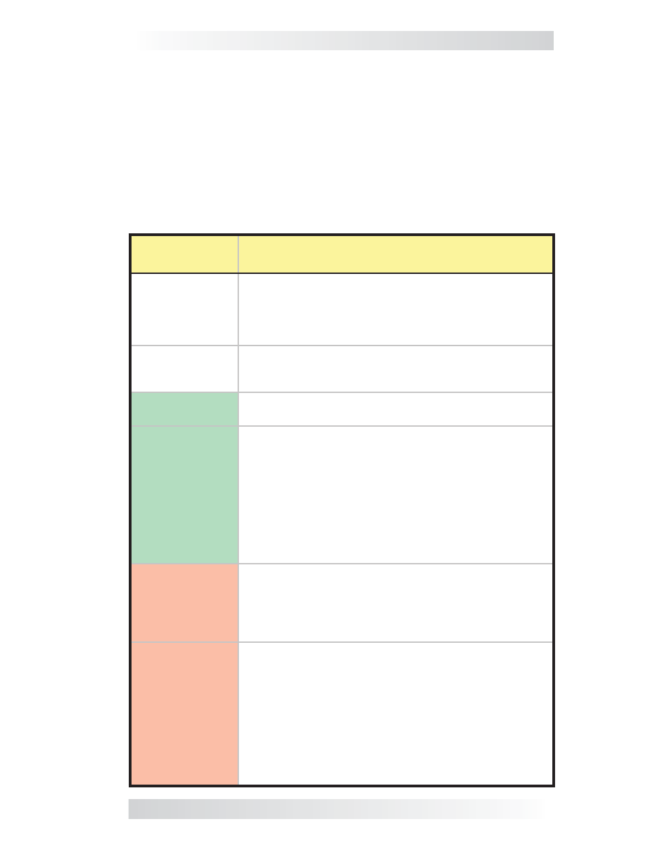
There is a bi-color LED indicator on the front of the Sense Module to indicate
the battery monitor’s status. When the Sense Module is fi rst powered up, the
LED blinks red and green while going through a self-test. Once the self-test
is complete, use the table below and the LED indicator on your BMK Sense
Module to determine the BMK’s operating status.
If the Sense Module does not function correctly, use Table 7-1 to help fi nd
a solution.
LED
Status
Meaning
OFF
1. No power to Sense Module. Check for correct DC
voltage (7 to 70 VDC) and correct polarity from pin
3 (-) to pin 4 (+) on the terminal block; or,
2. Ensure the terminal block is correctly seated into
the Sense Module.
Red ON, Green
ON, Red On,
Green ON
Power-up sequence (1 second interval between each
color). The Sense Module is performing a self-test
– this occurs when fi rst connected to power.
Green
ON
Normal operation: the Sense Module is correctly trans-
mitting and receiving with network devices.
Green
BLINKING
Not able to communicate with remote display.
A. If the remote/router display is off; refer to the re-
mote/router owner’s manual for troubleshooting. Ensure
the inverter is on and the correct communication cable
is connected to the REMOTE port on the inverter.
B. If the RC50 remote display is on; ensure the remote
display is revision 2.0 or higher. RC50 remote displays
with revisions prior to 2.0 are not compatible with the
ME-BMK.
Red
ON
The power-up sequence failed.
Unplug the 4-port terminal block from the Sense Module
and check for correct DC voltage on pins 3 and 4 (must
be between 7 to 70 volts DC depending on the nominal
voltage of the inverter).
Red
BLINKING
No communication, or an unrecognizable communication
on the network.
Check the communication cable; ensure it is connected
correctly. If the ME-BMK communication cable is miss-
ing, a standard 2-conductor telephone cable may be
temporarily substituted.
Important: Ensure the RJ11 connector is pushed into
the correct port; you should feel/hear a “click” when the
connection is made.
Table 6-1, LED Indicator Guide