Installation, 3 network connection with multiple devices – Magnum Energy Battery Monitor Kit ME-BMK User Manual
Page 11
7
© 2010 Magnum Energy, Inc.
Installation
Inv erting
DC 12.6V 5A
SEL ECT
TECH
AG S
M ETER
SETUP
SHO RE
I NVERTER
CHARG ER
I N V
C H G
FA U LT
P W R
O N / O F F
O N / O F F
M E -A GS -N (1
st
device)
R em ote C ontrol
(M E - R C50 w ith rev is ion of ≥2.0,
M E - A R C 50, or M E - R TR router)
M agnum Inverter /C harger
Phone
splitter
M E -B M K (2
n d
device)
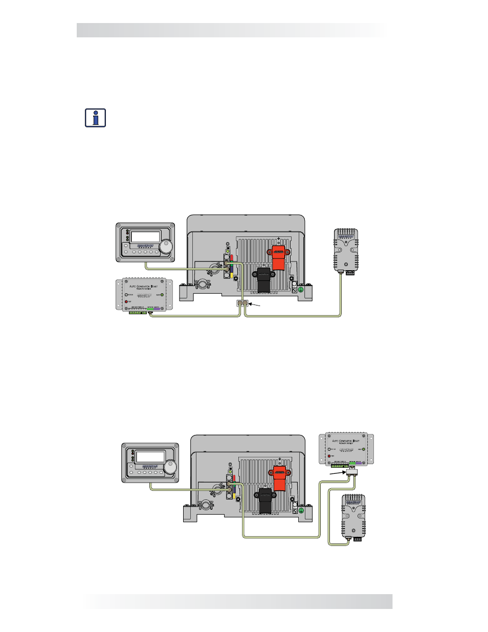
2.3 Network Connection with Multiple Devices
If you are using more than one Magnum Energy networked device, a 4-wire
phone-splitter is required to connect the network devices. It is possible to
interconnect the devices in two confi gurations; either in a Star or a Daisy
Chain confi guration.
Info: Before deciding on which confi guration to use, review the dif-
ferences in installation and ease of troubleshooting.
• Star Confi guration - In this arrangement, all the network devices con-
nect to the inverter’s Network port via a phone-splitter, using individual cable
runs (see Figure 2-4). Since each device is independently connected to the
inverter’s Magnum Net or Network port, problems in a cable or a device can
be easily isolated; and, if there is a cable failure to one device it does not
bring down all the other devices.
Figure 2-5, Multiple Network Devices - Daisy Chain Configuration
Inv erting
DC 12.6V 5A
S E L E CT
TECH
AG S
M ETER
SETUP
SHO RE
I NVERTER
CHARG ER
I N V
C H G
FA U LT
P W R
O N /O F F
O N /O F F
M E -B M K
R em ote C ontrol
(M E - R C50 w ith rev is ion of ≥2.0,
M E - A R C 50, or M E - R TR router)
M E -A GS -N
M agnum Inverter /C harger
P hone -splitter
• Daisy Chain Confi guration – In this arrangement, the network devices are
linked in a series (see Figure 2-5). If using this confi guration, the ME-AGS-N
must be the fi rst device connected to the inverter’s Magnum Net or Network
port – followed by the ME-BMK.
Figure 2-4, Multiple Network Devices - Star Configuration