Magnum Energy AGS Stand Alone (ME-AGS-S) User Manual
Page 6
3
© 2013 Magnum Energy, Inc.
1.1.3 AGS
Controller
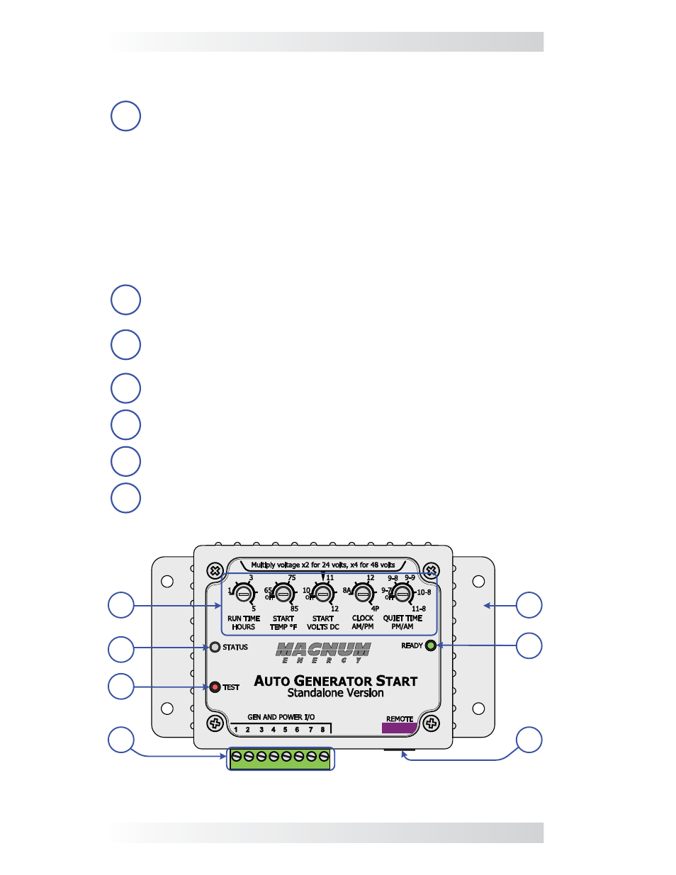
The controller provides adjustments and the generator’s wiring connections.
1
AGS Adjustments (x5) – The thumb wheel adjustments allow the
AGS to be confi gured to your specifi c system preferences.
• RUN
TIME
HOURS – determines the length of time the generator
runs once the generator has automatically started.
• START
TEMP
°F – allows you to enable and set a high temperature
value that causes the generator to automatically start.
• START VOLTS DC – allows you to enable and set a low battery
voltage value that causes the generator to automatically start.
• CLOCK AM/PM – determines the correct time, which in turn
allows the Quiet Time feature to function correctly.
• QUIET TIME PM/AM – used to prevent the generator from
starting during specifi c hours.
2
STATUS Indicator – this bi-color (green or red) LED indicator
illuminates to provide information on AGS operation.
3
TEST Switch – a momentary pushbutton switch that allows the
AGS system to be tested for correct wiring and generator start/stop
operation.
4
Wiring Terminal Block – this 8-port friction-fi t connector powers
the AGS and connects the generator’s start/stop and run sense wires.
5
Mounting Flange – used to secure the inverter to a shelf or wall.
6
READY Indicator – this green LED indicator illuminates to indicate
that the AGS is powered and the remote switch is connected.
7
REMOTE Connection Port (purple label) – a RJ12 port which
provides the connection point for the remote switch.
6
7
5
1
2
3
4
Figure 1-3, ME-AGS-S Controller Features
Introduction