0 setup, 1 internal settings, Setup – Magnum Energy AGS Stand Alone (ME-AGS-S) User Manual
Page 20: Figure 3-2, dc voltage settings, Figure 3-1, inside the ags controller
17
© 2013 Magnum Energy, Inc.
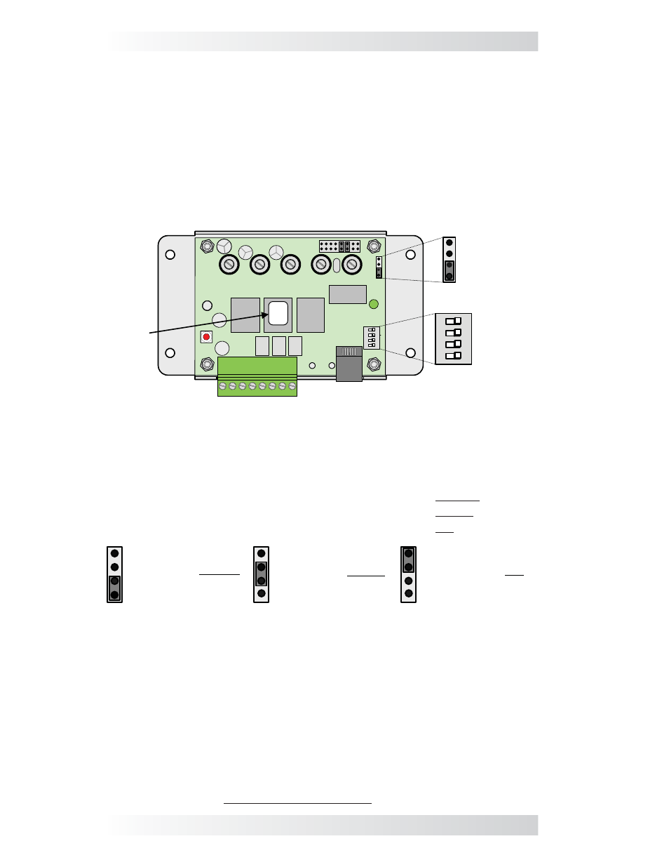
INPUT DC VOLTAGE Setting: The INPUT DC VOLTAGE setting is determined
by connecting two small pins with a small black plastic box (i.e., jumper). This
setting can be confi gured for 12, 24, or 48 VDC operation, which is determined
by the nominal DC voltage connected to Terminals 3 and 4 on the AGS.
•
For 12-volt DC operation, position the jumper on the bottom two pins.
•
For 24-volt DC operation, position the jumper on the middle two pins.
•
For 48-volt DC operation, position the jumper on the top two pins.
INPUT DC
VOLTAGE
Setting
12/24/48V
ON
4
3
2
1 13
4
2
ON
4
3
2
1
GEN
TYPE
Setting
RY1 RY2
RY3
Revision
Label
12/24/48V
Rev
##
(Default: 12V)
(Default: QD mode)
12 VDC Operation
(jumper on bottom
two pins)
**default setting**
24 VDC Operation
(jumper on middle
two pins)
48 VDC Operation
(jumper on top
two pins)
3.0 Setup
This section provides information on AGS settings and shows you how to
adjust these settings.
3.1 Internal
Settings
On the AGS controller, unscrew the four top screws and remove the plastic
cover to access an input DC voltage jumper and a 4-position DIP (Dual In-line
Package) switch. The INPUT DC VOLTAGE jumper position determines the con-
troller’s DC operating voltage. The DIP switch confi guration is used to select the
GEN TYPE which determines how the internal relays operate to automatically
start and stop the generator.
Figure 3-2, DC Voltage Settings
GEN TYPE Setting: The GEN TYPE setting is determined by a DIP switch,
which is actually 4 small switches that can be turned to the ON or OFF
position. The position of each of these 4 small switches is used to determine
the open and close timing sequence for the three internal AGS relays (RY1,
RY2 and RY3). The multiple positions of the DIP switch allow a wide range of
generator start/stop circuit confi gurations.
After determining the appropriate start/stop timing sequence for your
generator, use Table 3-1 to determine and set the correct GEN TYPE setting
for your generator’s start/stop requirements.
For examples and assistance in viewing which GEN TYPE setting is used for
specific generators, view the “ Generator Wiring Diagrams” under the Service
and Support area at www.magnumenergy.com.
Figure 3-1, Inside the AGS Controller
Setup