6 warning label, 7 common me-ags-s generator wiring diagrams, Warning – Magnum Energy AGS Stand Alone (ME-AGS-S) User Manual
Page 16
13
© 2013 Magnum Energy, Inc.
Installation
2.6 Warning
Label
It might be falsely assumed that it is safe to perform maintenance on the
generator or the electrical panel because the generator is off. However, the
AGS system can automatically turn on the generator and power the panel.
Two warning labels (Figure 2-8) are provided to inform all personnel that an
Automatic Generator Starting device is installed in your electrical system.
Place one label in a clearly visible location at the generator and the other
label at the electrical panel that is being powered by the generator.
WARNING: To prevent harm to servicing personnel, e
nsure the gen-
erator and AGS are properly disabled (i.e., remove the starting battery
from the generator and remove all power to the AGS by u
nplugging
the green 8-port friction-fi t terminal block from the controller
) prior to
performing maintenance on the generator or electrical panel.
2.7
Common ME-AGS-S Generator Wiring Diagrams
The most common generator starting/run/stop circuits can be divided into
three major types: two-wire, three-wire “momentary”, or three-wire “main-
tain”. The following generator wiring diagrams are provided to give examples
of these generator types.
Info: The term “three-wire” refers to the minimum number of wires
required to control the starter motor and to run the generator—more
than three wires may actually be needed.
Shown in Figure 2-9, the “two-wire” generator types integrate the control
circuits for start-up, running and stopping. The generator starts and runs when
two “control” wires are connected, and stops when they are disconnected.
Shown in Figure 2-10, the “three-wire momentary” generator types use a
three-position momentary type switch that controls their operation. To start
the generator, the switch is momentarily held to the START position. This
energizes the ignition system and cranks the starter motor. Once the engine
has started, the START switch is released and it returns to a center position
(i.e., “momentary” run control). To shut down the generator, the switch is
held to the STOP position until the engine dies. Once the switch is released,
it returns to the center position (i.e., “momentary” stop control).
Shown in Figure 2-11, the “three-wire maintain” generator types use an au-
tomotive type starting circuit. Operating a switch that is fi rst turned to a RUN
position and then momentarily held to a START position to start the generator.
Once the engine has started, the switch is released and it returns to the RUN
position (i.e., “maintain” run control). To shut down the generator, the switch
is moved to the OFF position (i.e., “maintain” stop control).
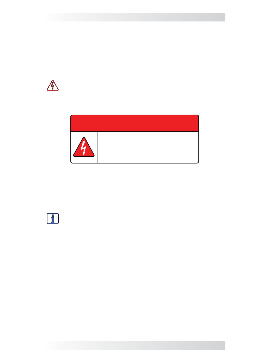
Figure 2-8,
Warning Label
This electrical system is equipped with an
Automatic Generator Starting (AGS) device and/or
an inverter. Disconnect all AC and DC power to the
AGS and/or inverter before performing any service
to the electrical system. Failure to do so can result
in shock causing serious injury or death.
PN: 62-0002 Rev A
WARNING