Ry2 ry3 relays inside the ags controller – Magnum Energy AGS Stand Alone (ME-AGS-S) User Manual
Page 15
© 2013 Magnum Energy, Inc.
12
Installation
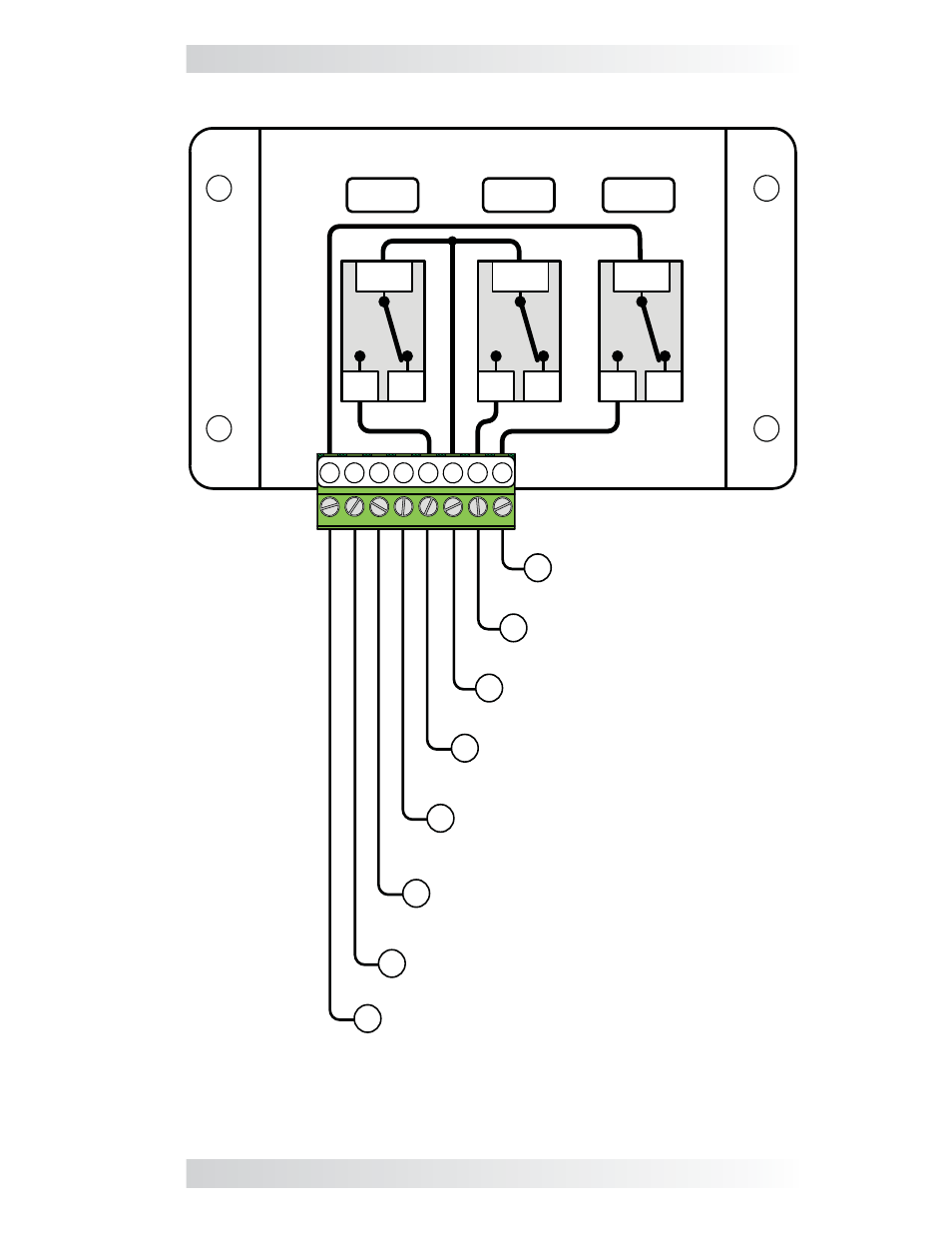
Figure 2-7, Wiring to the AGS Controller’s Terminal Block
1
2 3 4 5 6 7 8
RY1
NC
COM
NO
NC
COM
NO
NC
COM
NO
Positive DC voltage input
[(positive terminal from monitored
battery bank (9-64 VDC)]
Negative DC voltage input
(negative/ground terminal from
monitored battery bank)
Run Sense input (10 - 40 volts DC only
when gen is running)
Common (COM) contact on Relay 3 (RY3)
Normally Open (N.O.)
contact on Relay 3 (RY3)
Common (COM) contact on
Relay 1 (RY1) and Relay 2 (RY2)
Normally Open (N.O.)
contact on Relay 2 (RY2)
Normally Open (N.O.) contact
on Relay 1 (RY1)
8
7
1
2
3
4
5
6
RY2
RY3
Relays Inside the AGS controller