4 connecting the communication cable, White blue tab tab – Magnum Energy AGS Stand Alone (ME-AGS-S) User Manual
Page 11
© 2013 Magnum Energy, Inc.
8
Installation
2.4
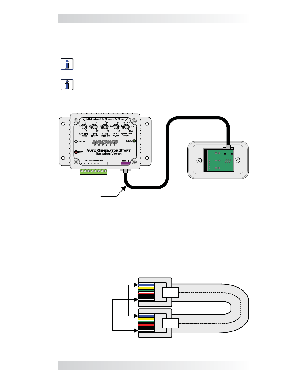
Connecting the Communication Cable
After connecting one end of the communication cable to the back of the
AGS remote switch, connect the other end of the cable to the REMOTE port
(purple label) on the AGS controller (see Figure 2-4).
Info: The communication cable is a 6-conductor, fl at, data stan-
dard with RJ12 (6-position/6-wire) connectors on each end
(see Figure 2-5).
Info: The 25’ communications cable may be extended to a maximum
of 250 feet if needed
.
ME-AGS-S Controller
Remote Switch
(backside)
Communications
Cable
Figure 2-4, Communication Cable Connection
Figure 2-5, Communication Cable (Data Type)
123
4
56
123
4
56
white
blue
TAB
TAB
same colors
from top
to bottom
(tabs facing
toward you)
2.4.1 Communication
Cable
The 6-conductor communications cable has a RJ12 (6-position/6-wire) con-
nector on each end and is wired as a data type cable. This means that when
the RJ12 connectors are held side by side with both of the connector tabs
facing the same way, the color of the conductors in each connector is the
same from top to bottom (as shown in Figure 2-5).