Surface configuration – clock control & position, Surface configuration – timer control & position, Logitek – Logitek Electronic Systems Artisan User Manual
Page 62
Logitek
Appendix E
Additional Protocol Commands
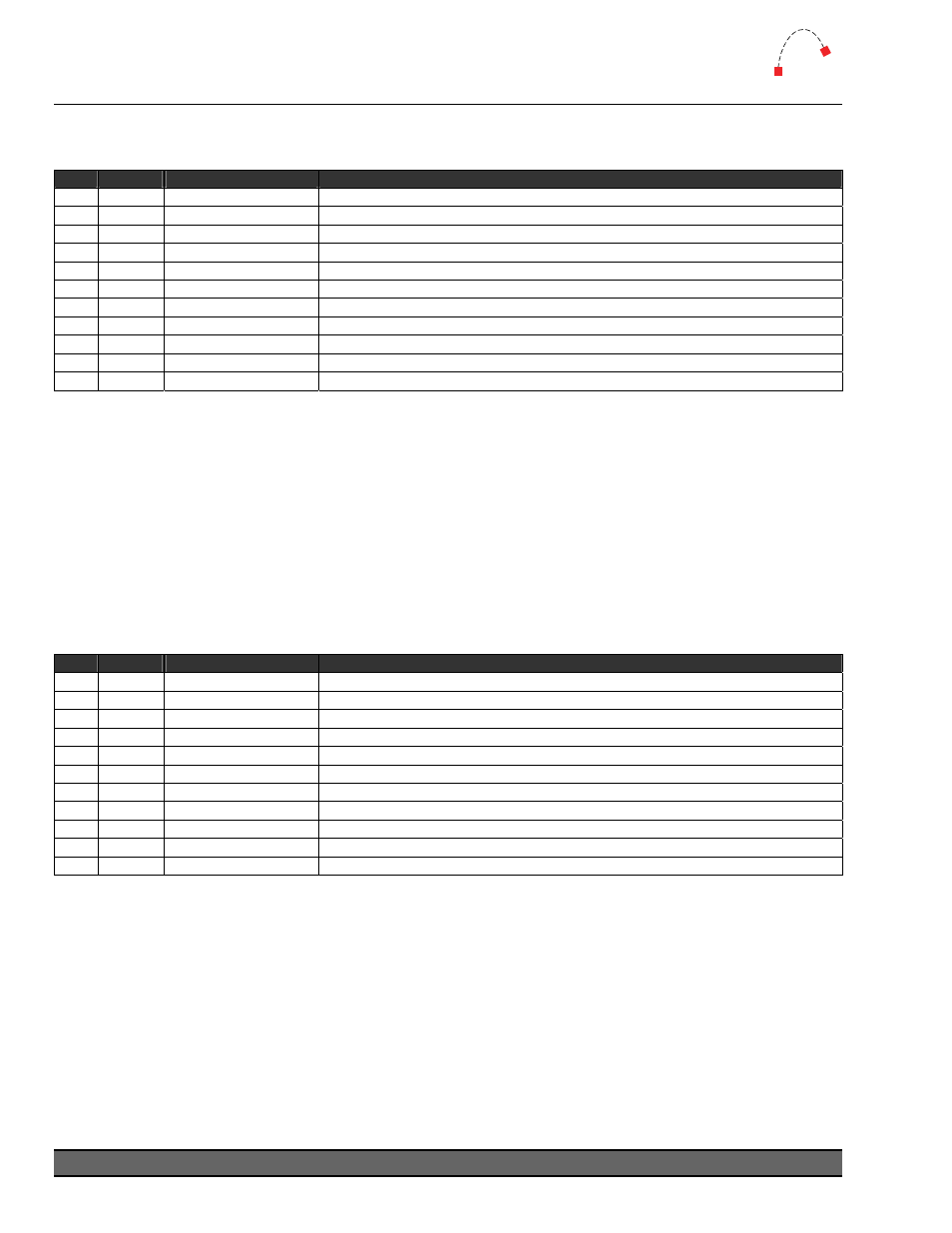
Surface Configuration – Clock Control & Position
Used to control the position and settings of the Artisan time-of-day clock. (v2.0 and later)
Seq
Byte
Description
Notes
1
<02>
Start byte
2
<09>
Bytes to follow
3
Command = Set Effect
4
Device Number
Device Number of Meter Bridge in hex (53 = Port 1)
5
<41>
Type = Surface Config
6
<0B>
Command = Set Clock
7
Data Byte = Mode
<00> = Off
<01> = On
(default = 01)
8
Data Byte = Type
<00> = Big
<01> = Small
(default = 00)
9
Data Byte = X Pos
<00> to
(default = 21h / 33d)
10
Data Byte = Y Pos
<00> to
11
Data Byte = LCD #
<01> to <06> = LCD screen number, from left to right
(default = 01)
The following example will put the Artisan clock in its default position on LCD screen #1:
02 09 AE 53 41 0B 01 00 21 50 01
TIP: The
Artisan clock should be addressed to CHAN73 LINE15, and then positioned
using the command above. If the clock data is sent to another line, the clock will
display as a standard text clock as per Numix and Remora surfaces.
Surface Configuration – Timer Control & Position
Used to control the position and settings of the Artisan timers. (v2.0 and later)
Seq
Byte
Description
Notes
1
<02>
Start byte
2
<09>
Bytes to follow
3
Command = Set Effect
4
Device Number
Device Number of Meter Bridge in hex (53 = Port 1)
5
<41>
Type = Surface Config
6
Command = Timer No. <15> = Timer 1 Control <16> = Timer 2 Control
7
Data Byte = Mode
<00> = Off
<01> = On
(default = 01)
8
Data Byte = Type
<00> = Big
<01> = Small
(default = 00)
9
Data Byte = X Pos
<00> to
(default = 21h / 33d)
10
Data Byte = Y Pos
<00> to
11
Data Byte = LCD #
<01> to <06> = LCD screen number, from left to right
(default = 05)
The following example will enable Timer #1 in big mode in its default position on LCD screen #5.
02 09 AE 53 41 15 01 00 21 50 05
Logitek Artisan Reference Manual
60