Chapter 1, Introduction, Front panel features – Lanner FW-7573 User Manual
Page 8
3
Introduction
Network Application Platforms
Chapter 1
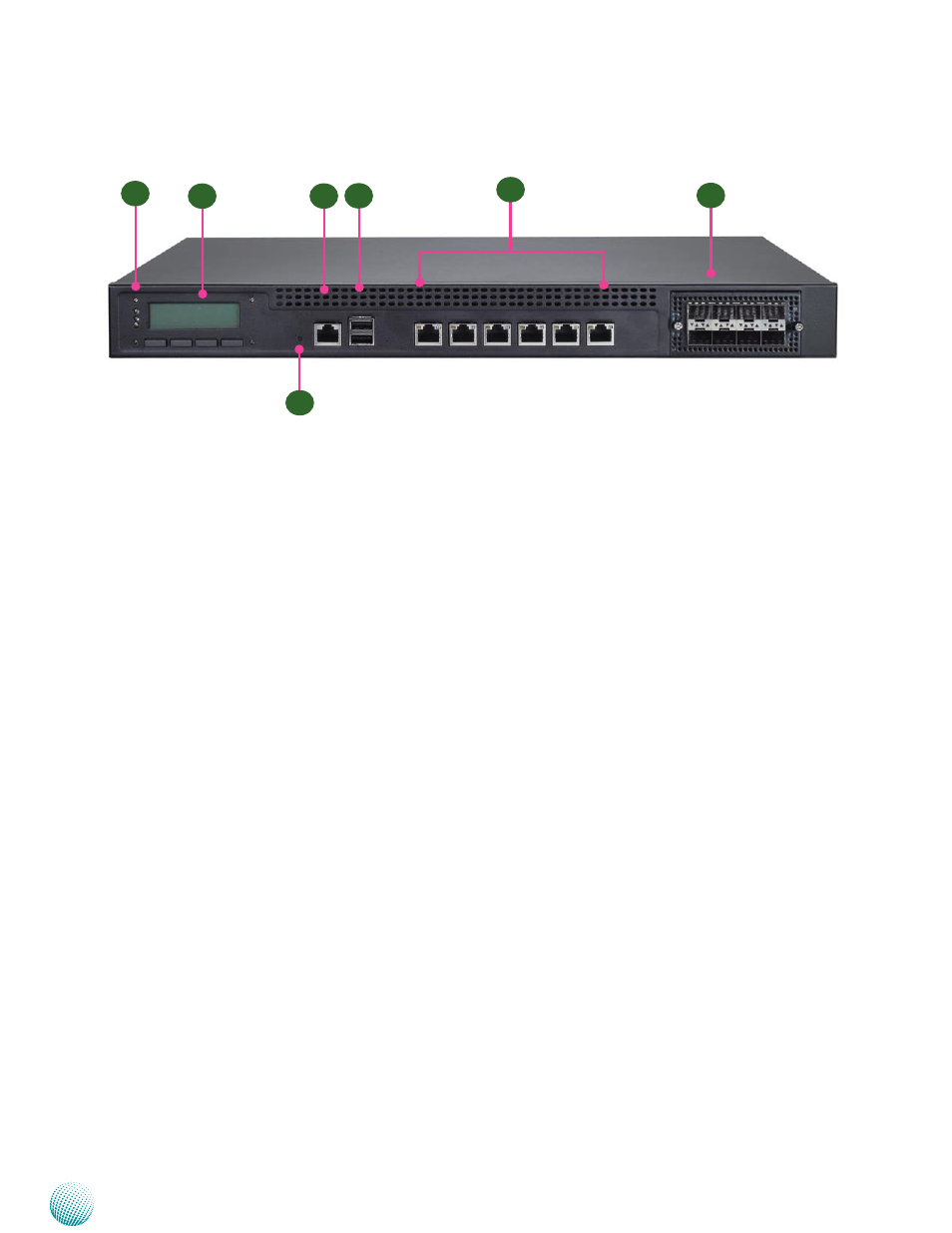
Front Panel Features
F1 Power/Status/HDD LED
Power: If the LED is on it indicates that the system is powered on. If it is off, it indicates that the system is powered off.
Status: This LED is programmable. You could program it to display the operating status with the following behavior:
If the LED is green, it indicates that the system’s operational state is normal. If it is red, it indicates that the system is
malfunctioning.
HDD: If the LED blinks, it indicates data access activities; otherwise, it remains off.
F2 LCD System Panel with Keypad
The LCD System Panel can be programmed to display operating status and configuration information. For more details or
sample programming code, please browse the Drivers and user’s manual CD.
F3 Reset Switch
The reset switch can be used to reboot the system without turning off the power. The reset switch can act as a software or a
hardware reset with jumper settings. The default is software reset. (Refer to Chapter 3 Motherboard Information.)
F4 Console Port
By using suitable rollover cable or RJ-45 to DB-9 console cable, you can connect to a computer terminal for diagnostic or
configuration purpose. Terminal Configuration Parameters: 115200 baud, 8 data bits, no parity, 1 stop bit , no flow control.
F5 Two USB 2.0 Ports
It connects to any USB devices, for example, a flash drive.
F6 Ethernet Ports (LAN1-LAN2: bypass pair; LAN3-LAN4: bypass pair; LAN5-LAN6: bypass pair
*
)
LINK/ACT (Yellow)
On/Flashing: The port is linking and active in data transmission.
•
Off: The port is not linking.
•
SPEED (Green/Amber)
Amber: The connection speed is 1000Mbps.
•
Green: The connection speed is 100Mbps
•
Off: .The connection speed is 10Mbps.
•
6 on-board Ethernet ports with 3 pairs of LAN bypass. These 6 GbE ports are provided by Marvell 88E1543 and Intel i210AT.
LAN5 is capable of Preboot eXecution Environment (PXE) (This feature needs to be enabled or disable in the BIOS; the default
is disabled). Three pairs (LAN1-LAN2, LAN3-LAN4, LAN5-LAN6) can be configured as LAN Bypass by using Lanner Gen3
Bypass technology when failure events occur. This feature can be enabled dynamically with a watch dog timer. Refer to your
F1
F2
F4
F5
F6
LAN1 LAN2
Marvell 88E1543 Marvell 88E1543 (bypassed pair)
LAN3 LAN4
Marvell 88E1543 Marvell 88E1543(bypassed pair)
LAN5 LAN6
Intel i210AT Intel i210AT (bypassed pair)
F7
F3