Chapter 3, Motherboard information – Lanner FW-7573 User Manual
Page 18
13
Motherboard Information
Network Application Platforms
Chapter 3
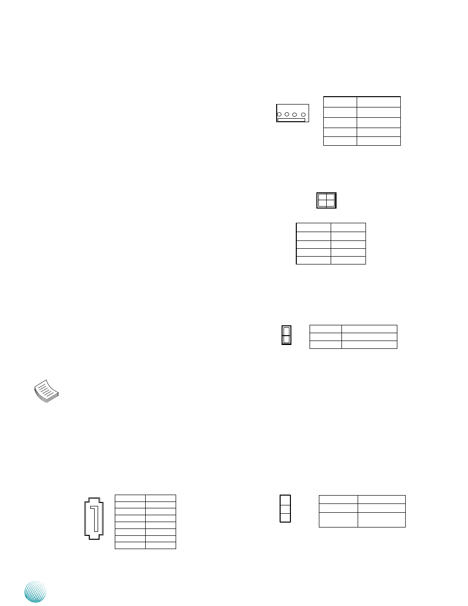
4-Pin SATA Power Connector (PS4P1, PS4P2)
Power-switch Connector (SW1): Power tact for booting
up the system.
AT Mode Power Button Connector (CONN1): It is for
connecting the power switch in AT mode
Reset Switch (SW2) and Reset Button Connector
(CONN2)
Hardware/Software Reset Function (J5): It is a pin
header to switch between hardware and software
reset function for the front panel reset button.
Hardware reset will reset the whole system while
software reset will reset the designated software to
its default value.
DIMM Socket (DIMM1/DIMM2): The 240-pin DDR3 DIMM
is for connecting the DDR3 1333/1600 memory. The
system can support up to 16 GB in maximum with
dual channel configuration. To activate dual channel,
insert memory in both DIMM1 and DIMM2 slot:
SATA
Connector
(SATA1/SATA2,
SATA6G_1,
SATA6G_2): It is for connecting a SATA harddisk to
be served as your system’s storage. The system can
accommodate 2 disk2 (2.5) with SATA Revision 2.0
(SATA1 and SATA2) and 3.0 standard (SATA6G_1,
SATA6G_2). The controller contains two modes
of operation—a legacy mode using I/O space, and
an AHCI mode using memory space. Software that
uses legacy mode will not have AHCI capabilities.
The AHCI (Advanced Host Controller Interface) is a
programming interface which defines transactions
between the SATA controller and software and
enables advanced performance and usability with
SATA. Platforms supporting AHCI may take advantage
of performance features such as no master/slave
designation for SATA devices—each device is treated
as a master—and hardware assisted native command
queuing. AHCI also provides usability enhancements
such as Hot-Plug.
Note:
You will need to configure your SATA as
1.
AHCI mode in the BIOS in order to use the
advanced features of SATA. To do this, access
the BIOS menu under IntelRCSetup->
South Bridge Chipset Configuration->SATA
Configuration.
Also, the hotplug enable/disable option is
2.
under the same SATA Configuration menu.
Enable the hotplug function explicitly in this
menu if you need it.
2
1
4
3
Pin No.
Signal
1
Ground
2
Ground
3
PS_ON#
4
PS_ON#
Pin No.
Signal
1
+12V
2
GND
3
Ground
4
5V
4 3 2 1
Pin No.
Signal
1
PS_ON#
2
GND
1
2
Pin No.
Signal
1
GND
2
TX_P
3
TX_N
4
GND
5
RX_N
6
RX_P
7
GND
7
6
5
4
3
2
1
Pin No.
Function
1-2
Hardware Reset
2-3
Software Reset
(Default)
1
3