Chapter 3, Motherboard information, Cf1 1 – Lanner FW-7573 User Manual
Page 17
12
Motherboard Information
Network Application Platforms
Chapter 3
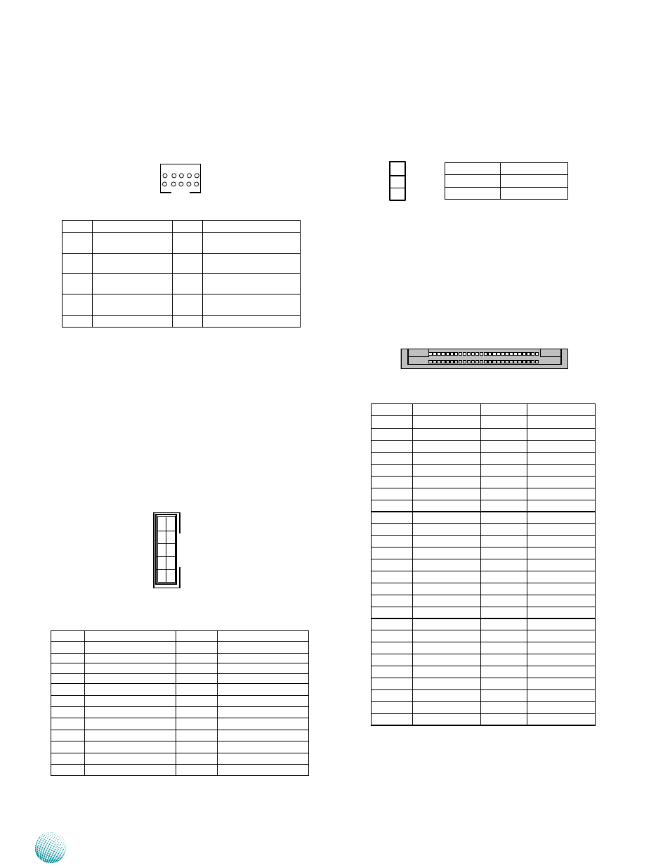
Serial Interface Connectors(COMB1): It is for
connecting the RS-232 serial port (COM2) interface
cable.
LAN 1~4: LAN Connector(RJ-45, provided by Intel Marvell
88E1543)
LAN 5~6 Connector (RJ-45, provided by Intel Ethernet
i210AT)
Parallel Interface for LCM (front LCD module) card
Connector (J4)
COMB1
Clear CMOS jumper (JBAT1): It is for clearing the CMOS
memory and system setup parameters by erasing
the data stored such as the system passwords in
the CMOS RAM.
CompactFlash Connector (CF2): It is for connecting a
Compact Flash card to be served as your system’s
storage. The connector is a CF Type II slot which could
fit both CF Type I or CF Type II cards.
Pin No.
Signal
1-2 (Default)
Normal
2-3
Clear CMOS
25 1
50 26
CF1
1
Pin No.
Signal
Pin No.
Signal
1
GND
26
CD1-
2
DATA3
27
DATA11
3
DATA4
28
DATA12
4
DATA5
29
DATA13
5
DATA6
30
DATA14
6
DATA7
31
7
CE1#
32
DATA15
8
A10
33
CE2#
9
OE#
34
VS1#
10
A9
35
IOR#
11
A8
36
IOW#
12
A7
37
WE#
13
CFVCC3
38
READY#
14
A6
39
CFVCC3
15
A5
40
CSEL
16
A4
41
VS2#
17
A3
42
RESET
18
A2
43
WAIT#
19
A1
44
INPACK#
20
A0
45
REG#
21
DATA0
46
DASP#
22
DATA1
47
DIAG#
23
DATA2
48
DATA8
24
WP
49
DATA9
25
CD2-
50
DATA10
GND
24
.
.
.
.
8
6
4
2
23
.
.
.
7
5
3
1
Pin No.
Signal
Pin No.
Signal
1
+5V
2
GND
3
LPT17
4
VEE
5
LPT14
6
LPT16
7
LPT3
8
LPT2
9
LPT5
10
LPT4
11
LPT7
12
LPT6
13
LPT9
14
LPT8
15
LCD-
16
VCC
17
KPA1
18
KPA2
19
KPA3
20
KPA4
21
LCM_RST
22
LED_GREEN
23
LED_YELLOW
24
HDD_LED-
Pin No.
Signal
Pin No.
Signal
1
Data Carrier Detect
(DCDB#)
2
Data Set Ready
(DSRB#)
3
Receive Data
(RXDB)
4
Request To Send
(RTSB#)
5
Transmit Data
(TXDB)
6
Clear To Send
(CTSB #)
7
Data Terminal Ready
(DTRB#)
8
Ring Indicator
(RIB#)
9
GND
10
Key
1 9
2 10
1
3