Jumper settings, Chapter 3, Motherboard information – Lanner FW-7565 User Manual
Page 17
12
Motherboard Information
Chapter 3
Network Application Platforms
M6
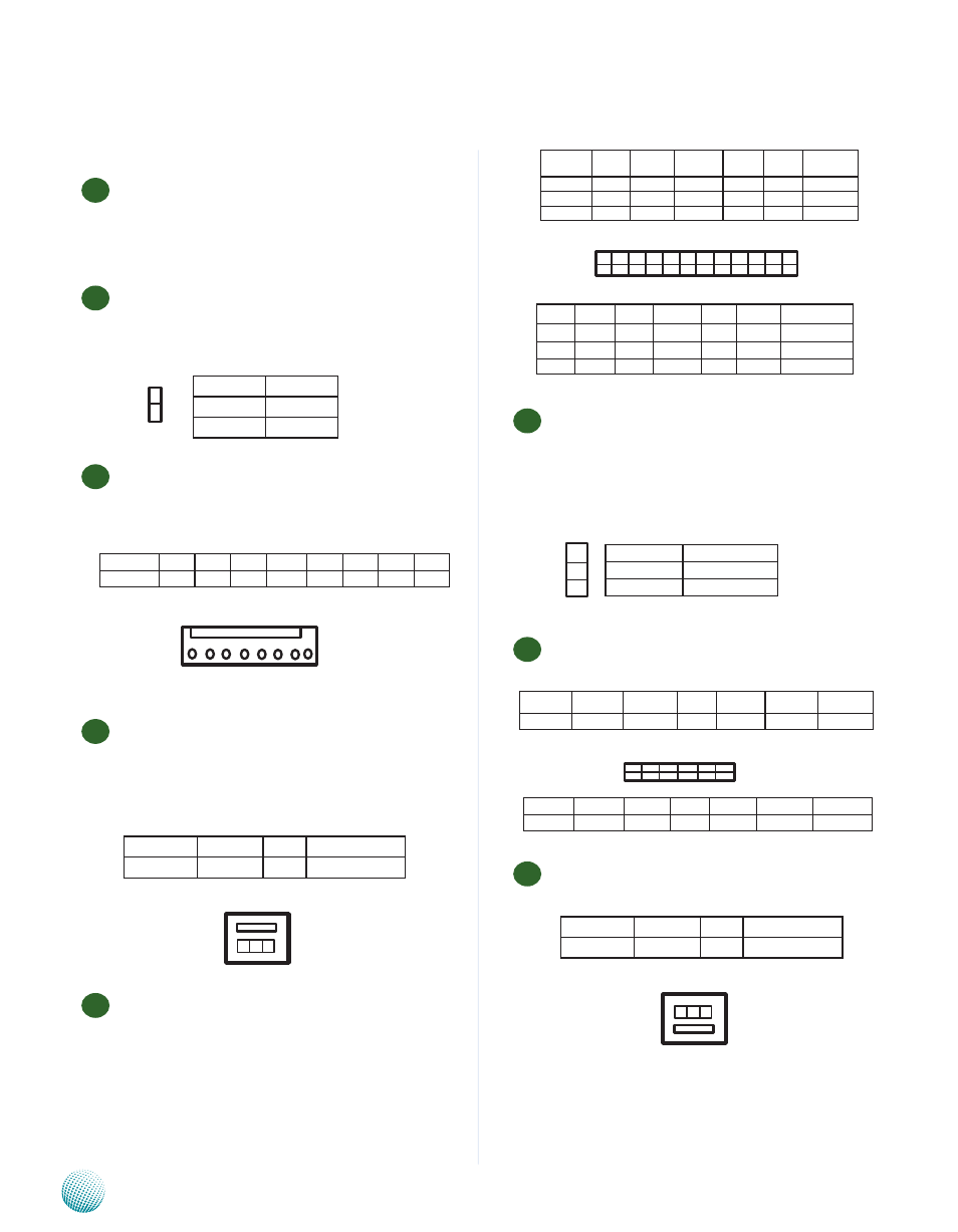
Hardware or Software Reset Jumper(JP2): The jumper
can be adjusted to be in either hardware or software
reset mode when the reset switch is pressed. The
hardware reset will reboot the system without turning
off the power. The software reset can be programmed
to reset a software to its default setting.
M7
VGA Interface (J1): It is for connecting the VGA
interface cable.
Auxiliary Fan Connector (FAN3): This connector is for
connecting any additional cooling fans.
Jumper Settings
M1
SO-DIMM Socket : It is for connecting the DDR2 667
memory (200 pin). Besides the 512MB/1G on-board
DDR2 667 SDRAM, the system can support up to a
total of 3GB.
M8
Power Switch Connector(CONN2): This connector
is for the system power button. Pressing the power
button turns the system on or puts the system in sleep
or soft-off mode depending on the BIOS settings.
M3
ATX Power Connector(PS1): The 8-pin connector is for
connecting ATX power supply plugs. Find the proper
orientation when inserting the plugs, for the supply
plugs are designed to fit these connectors in only one
orientation.
M4
Fan Connectors(FAN1/FAN2): The 3-pin header is for
connecting the system and CPU fan. The BIOS will
list the CPU and system fans’ monitored temperature
and speed under the menu of Hardware Health
Configuration. You could also configure the target
temperature to adjust the fan speed automatically.
M5
Front LCD Module Connector(J9): The 24-pin
connector is for connecting the front system panel.
1
2
Pin No.
Pin name
1
PANSW
2
GND
3 2 1
Function Ground +12V
Fan Status
PIN NO.
1
2
3
8 7 6 5 4 3 2 1
Function PSON 5VSB GND +3.3V +12V GND GND +5V
PIN NO.
8
7
6
5
4
3
2
1
23 21 19 17 15 13 11 9 7 5 3 1
24 22 20 18 16 14 12 10 8 6 4 2
GPIO
GND
K3
K1
LCD
LPD7 Function
23
21
19
17
15
13
PIN No.
LPD5
LPD3
LPD1
LAFD- LSTIN- VCC Function
11
9
7
5
3
1
PIN No.
12
10
8
6
4
2
PIN No.
LPD4 LPD2 LPD0
LINIT-
VEE IOGND FUNCTION
24
22
20
18
16
14
VCC3 VCC3
K4
K2
VCC
LPD6
Pin No.
Function
1-2 (Default)
Software Reset
2-3
Hardware Reset
1
2
3
PIN No.
1
3
5
7
9
11
Function
Red
Green
Blue HSYNC VSYNC DD_DATA
Function CRT ON
GND
GND
GND
GND
DD_CLK
PIN No.
2
4
6
8
10
12
2 4 6 8 10 12
1 3 5 7 9 11
M8
1 2 3
Function Ground +12V
Fan Status
PIN NO.
1
2
3