Motherboard layout, Chapter 3, Motherboard information – Lanner FW-7565 User Manual
Page 16
11
Motherboard Information
Chapter 3
Network Application Platforms
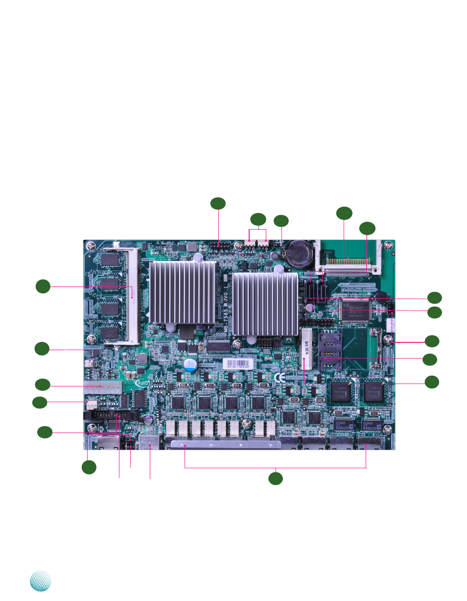
Motherboard Layout
The motherboard layout shows the connectors and
jumpers on the board. Refer to the following picture
as a reference of the pin assignments and the internal
connectors.
Compact Flash Connector
Fan1 and Fan2 Connec-
tor
Ethernet Ports
USB2.0 Ports
SO-DIMM
Socket
USB 3 and 4
Connectors
Mini PCI-E
Connector
SIM Card
connector
Power Switch Con-
nector
VGA Interface
Clear CMOS
ATX Power
Connector
Hardware and Software
Reset jumper
Serial Port Con-
nector
Reset Switch
M10
M1
Fan3
Connector
Keyboard and
Mouse Connec-
tors
M3
M7
M9
M12
M13
M14
M15
M16
M5
M11
M2
M4
M6
Serial Port
Connector
M17
M8