Appendix a, Using the ignition system manager (ism) – Lanner LVC-5570 User Manual
Page 32
32
Using the Ignition System Manager (ISM)
Embedded and Industrial Computing
Appendix A
Appendix A:
Using the Ignition System
Manager (ISM)
The Ignition System Manager (ISM) is a software that
can monitor the system’s voltage level and configure the
features that the Power Ignition Module provides.
For sample ISM code, see ISM folder under LVC-5570 Utility
on the Driver and Manual CD.
Running the Program
Just double click the ISM.exe to launch the ISM.
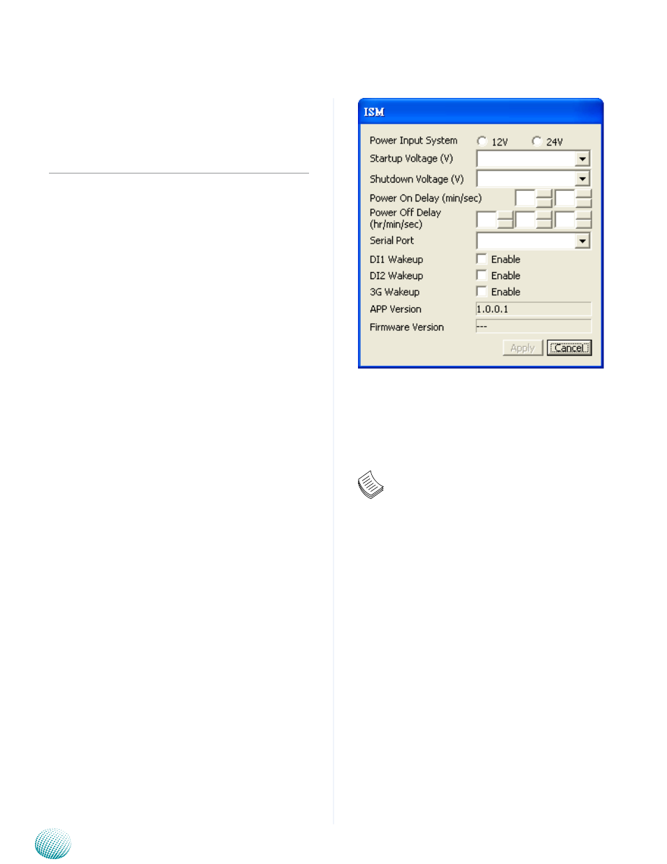
The program can configure the following values:
Voltage: It shows the current power system.
Power Input System: Select either 12V or 24V for vehicular
power input.
Startup Voltage (V): If the DC-in voltage is not higher
than this value, the system will not be able to start up.
Shutdown Voltage (V): If the DC-in voltage is lower than
the shutdown voltage, the system will start shutdown
process automatically. (Refer to selector 2 of SW1 dip
switch on the LEK-IG1 board)
Power-on Delay (min/sec): Select power-on delay value
to indicate the time to delay powering on the system.
(Refer to the flow chart in Chapter 4)
Power-off Delay (hr/min/sec): Select power-off delay
value to indicate the time to delay powering off the system
(Refer to the flow chart in Chapter 4)
Serial Port: Select the serial communication port for the
ISM. Choose COM5.
D1/D2 Wakeup: Digital input triggering to enable
automatic wake-up function. Select this option and it will
start the system automatically once an input has been
triggered.
3G Wakeup:
3G SMS/Ring wake-up to enable automatic
wake-up function. Select this option and it will start the system
automatically through 3G internet service.
After you have made changes, click Apply to apply the
changes to the Ignition controller or Cancel to cancel the
changes.
Click Cancel to exit the ISM program.
Note:
You will have to enable (the default is enabled)
1.
the selector 2 (Low Voltage Detection) of SW1
dip switch on the LEK-IG1 to enable automatic
shutdown function. (Refer to Select MCU Detect
Function for power ignition behavior (SW1) in
Chapter 3 Board Layout).
DI1/DI2 Wakeup function is detected via pin
2.
12/13 of J3 (DIO)
3G Wake-up function is enabled via MCARD1
3.
Mini-PCIe connector.
Refer to the flow charts in Chapter 4 for more
4.
information.
.
COM5