Chapter 3, Board layout, Connectors and jumpers list – Lanner LVC-5570 User Manual
Page 18
18
Board Layout
Chapter 3
Embedded and Industrial Computing
Connectors and Jumpers List
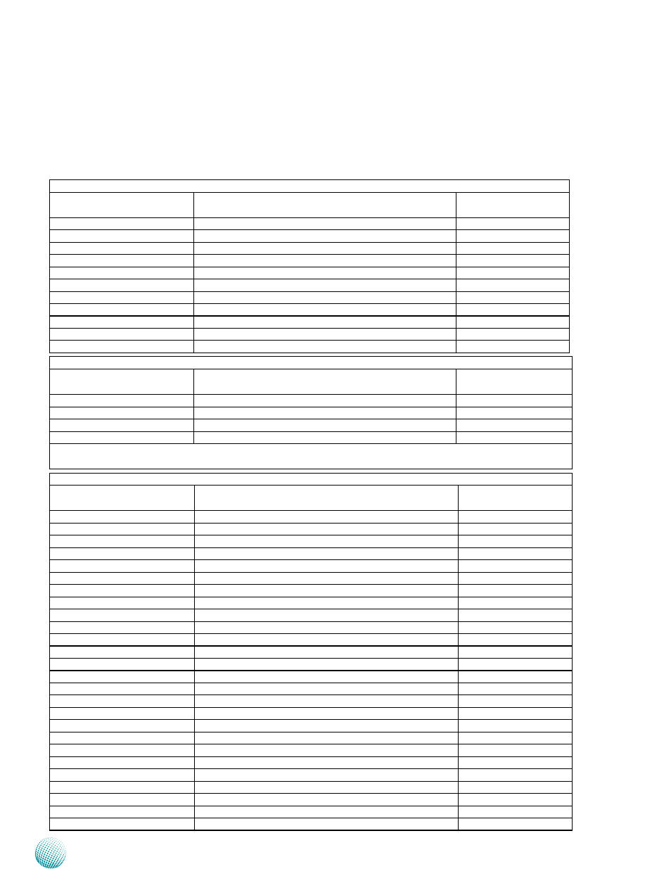
The tables below list the function of each of the board
jumpers and connectors by labels shown in the above
section. The next section in this chapter gives pin
definitions and instructions on setting jumpers.
Table 3.1 Connector List for LEK-IOA6 Board
Labels
Function
Pin Definition Refer-
ence Page
CN2
DC Relay Bypass
P21
COM1
RS232/422/485 Serial Port
P19
COM1
3G Audio Connector (D-Sub)
P19
COM2
RS232/422/485 Serial Port
P19
COM2
HD Audio Connector (D-Sub)
P19
HDDSL1
Enable/disable onboard SSD
P21
J3
DIO port
P20
J6
Select MCARD1 Voltage for Module Sierra MC809x
P21
SCT1/SCT2
Select COM1 Protocol Setting
P19
SCT3/SCT4
Select COM2 Protocol Setting
P19
SIM1/SIM2
SIM Card Reader (along with MCARD1 for 3G service)
P21
Table 3.2Connector List for LEK-IG1 Board
Labels
Function
Pin Definition Refer-
ence Page
CN1
MCU Programming Connector
P27
IGNITION1
Ignition Control Connector
P27
IGN_CON1
Power Connector
P27
SW1
Power Ignition Behavior Switch
P26
The ignition board also equips with jumpers that can be switched to enable or disable automatic power management
control.
Table 3.3 Connector List for LEB-5570 Board
Labels
Function
Pin Definition Refer-
ence Page
CMOS1
Cleaning CMOS Data Including RTC
P25
CMOS2
Cleaning CMOS Data Only
P25
COMSLT1
Daughter board LEK-IOA6 enable/disable
P25
COMSLT2
Daughter board LEK-IG1 enable/disable
P25
CN3
Power Connector with Power -ignition Control
P25
DCJK1 (optional)
Optional DC Jack Type of Power Connector
P25
DVID1
DVI-D Connector
P23
FAN1/FAN2
System Fan Connector
P23
Front1
Front Panel Function Pin Header
P22
HDMI1
HDMI Port
P23
Ignition1
Connector for power Ignition Control
P26
J1
PEG16X Lane Function Selection
P24
KBM1
PS/2 Keybaord and Mouse Connector
P26
LAN1/LAN2
Ethernet Connector 1/Ethernet Connector 2
P25
LPC1
Low Pin Count Interface
Reserved for factory use
MIO1
COM and Audio Expansion Card Connector
P22
MPCIE1
Mini-PCIe Connector
P24
MPCIE2
Mini-PCIe Connector
P24
RST1
Reset Button
P24
SATA1/SATA2
Serial-ATA Connector (SATA2 supports SATA-DOM)
P22
SATA_PWR1
SATA Power Connector
P22
SATA_PW2
Switch for SATA port 2 power state
P22
SIM1
SIM Card Reader
P25
SPI1
Serial Peripheral Interface Bus
Reserved for factory use
USB1/USB2/USB3
USB Type A Connector #0,1; #2,3; #4,5
P25
VGA1
VGA Port
P23