Chapter 3, Board layout, Jumper settings – Lanner LVC-5570 User Manual
Page 19: Sct1, Sct3 sct4
19
Board Layout
Chapter 3
Embedded and Industrial Computing
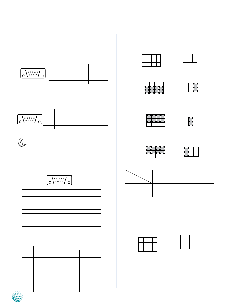
SCT1, SCT2: Select COM1 Protocol Setting
RS-232
RS-422
RS-485
Switch
Protocol
SCT1
SCT2
RS-232 (default)
1-5, 2-6, 3-7, 4-8
1-2
RS-422
5-9, 6-10, 7-11, 8-12
3-4
RS-485
5-9, 6-10, 7-11, 8-12
5-6
SCT3, SCT4: Select COM2 Protocol Setting
Jumper Settings
3G Audio Connector (COM1): a D-sub 9 male connector
for 3G Audio
Line-out Audio Jack (COM2): a D-sub 9 male connector
for HD Audio
Note: The driver for the VGA and Audio ports
should be installed with the following order:
Chipset INF->Graphic->Audio
COM1 RS-232 Serial Port(COM1): a RS-232/422/485 port
through the D-SUB9 connector.
RS-232/422/485 Serial Port(COM2): a RS-232/422/485
port through the D-SUB9 connector.
6 7 8 9
1 2 3 4 5
Pin No.
Function
Pin No.
Function
1
3G_MIC_R
6
3G_MIC_L
2
N/A
7
N/A
3
3G_EAROR
8
GND_AUD1
4
3G_EAROL
9
GND_AUD1
5
N/A
10
N/A
LEK-IOA6 Board
Pin No.
Pin Name
RS-232
RS-422
RS-485
1
DCD
TXD-
DATA-
2
RXD
TXD+
DATA+
3
TXD
RXD+
4
DTR
RXD-
5
GND
6
DSR
7
RTS
8
CTS
9
RI
Pin No.
Pin Name
RS-232
RS-422
RS-485
1
DCD
TXD-
DATA-
2
RXD
TXD+
DATA+
3
TXD
RXD+
4
DTR
RXD-
5
GND
6
DSR
7
RTS
8
CTS
9
RI
SCT2
1
2
SCT1
9
5
1
12
8
4
9
5
1
12
8
4
9
5
1
12
8
4
9
5
1
12
8
4
SCT3
SCT4
6 7 8 9
1 2 3 4 5
6 7 8 9
1 2 3 4 5
Pin No.
Function
Pin No.
Function
1
AUDIO_OUT_R
6
AUDIO_OUT_L
2
N/A
7
N/A
3
AMPOUT_R
8
GND_AUD
4
AMPOUT_L
9
GND_AUD
5
N/A
10
N/A
5
6
1
2
1
2
1
2
5
6
5
6
5
6
12
8
4
9
5
1
1
3
5
2
4
6