Chapter 5, Chapter 5: hardware setup, Hardware setup – Lanner LVC-5570 User Manual
Page 29: Preparing the hardware installation
29
Hardware Setup
Chapter 5
Embedded and Industrial Computing
Chapter 5:
Hardware Setup
Preparing the Hardware Installation
To access some components and perform certain service
procedures, you must perform the following procedures
first.
WARNING: To reduce the risk of personal injury,
electric shock, or damage to the equipment,
remove the power cord to remove power from
the server. The power switch button does not
completely shut off system power. Portions of the
power supply and some internal circuitry remain
active until power is removed.
Unpower the LVC-5570 and remove the power cord.
1.
Unscrew the 4 threaded screws from the top cover.
2.
Open the cover.
3.
Note:
If the CPU thermal pad mounting breaks apart,
use your hands to reattach the falling parts and
stick them together.
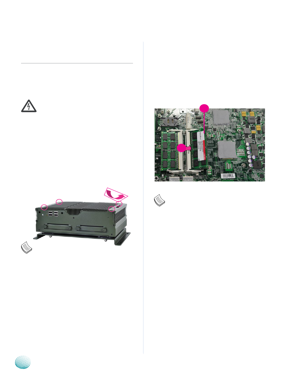
Installing the System Memory
The motherboard supports DDR3 memory to meet the
higher bandwidth requirements of the latest operating
system and Internet applications. It comes with two
Double Data Rate Three (DDR3) Small Outline Dual Inline
Memory Module (SO-DIMM) socket.
Align the memory module’s key with the SO-DIMM
1.
socket’s key.
Install the SO-DIMM.
2.
Note:
The system can support memory of DDR3 SO-
DIMM up to 16 GB in maximum with 2 SO-DIMM
sockets.
1
2