Chapter 2, System components, Front components – Lanner LVC-2000 User Manual
Page 9
9
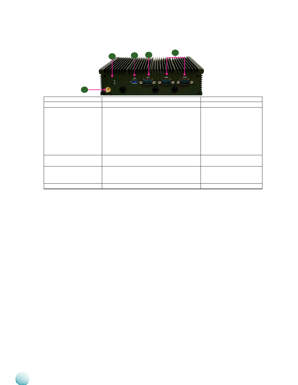
System Components
Chapter 2
Embedded and Industrial Computing
Component
Description
Pin Definition Reference
F1 GPS Antenna
Reserved for GPS antenna
F2 HDD/SSD and
Power LED (Green)
HDD/SSD
•
Blinking: means data access activities
•
Off: means no data access activities or no
hard disk present
Power
•
On: The computer is on.
•
Off: The computer is off .
F3 USB 3.0 Ports
USB 3.0 type A connectors. There are additional
2 USB 2.0 ports with pin headers
USB2 on page
F4 CAN bus
CAN bus connector for controller area network
communication. It supports J1939 &J1708
standards.
CAN1 on page
F5 COM1/COM2
RS232 ports for serial communication
COM1/COM2 on page
Front Components
F1
F2
F3
F4
F5
See also other documents in the category Lanner Computer hardware:
- LVC-5000(N4) (42 pages)
- LVC-5550S (41 pages)
- LVC-5570 (48 pages)
- LVC-5770 (49 pages)
- FW-6432 (16 pages)
- FW-7525 (41 pages)
- FW-5330 (38 pages)
- FW-6486 (18 pages)
- FW-6436 (19 pages)
- FW-7573 (44 pages)
- FW-7568 (52 pages)
- FW-7540 (47 pages)
- FW-8759 (47 pages)
- FW-7581 (23 pages)
- FW-8758 (42 pages)
- FW-7610 (44 pages)
- FW-8756 (24 pages)
- FW-7575 (48 pages)
- FW-8760 (53 pages)
- FW-8877 (46 pages)
- FW-8892 (58 pages)
- FW-8893C (49 pages)
- FX-3411 (48 pages)
- FW-8894 (31 pages)
- FW-8771 (47 pages)
- RS12-38800 (64 pages)
- MR-320 (20 pages)
- FX-3210 (54 pages)
- MR-301 (16 pages)
- MR-350 (12 pages)
- MR-330A (16 pages)
- MR-730 (18 pages)
- VES-220 (19 pages)
- VES-270 (19 pages)
- VES-310 (15 pages)
- VES-310 V2 (20 pages)
- VES-500 (21 pages)
- EM-F345 (30 pages)
- VES-8X2 (16 pages)
- VES-8X6 (17 pages)
- LEC-2026 (67 pages)
- LEC-2010 (65 pages)
- LEC-2136 (20 pages)
- LEC-2050 (38 pages)