Chapter 2, System components, Rear components – Lanner LVC-2000 User Manual
Page 10
10
System Components
Chapter 2
Embedded and Industrial Computing
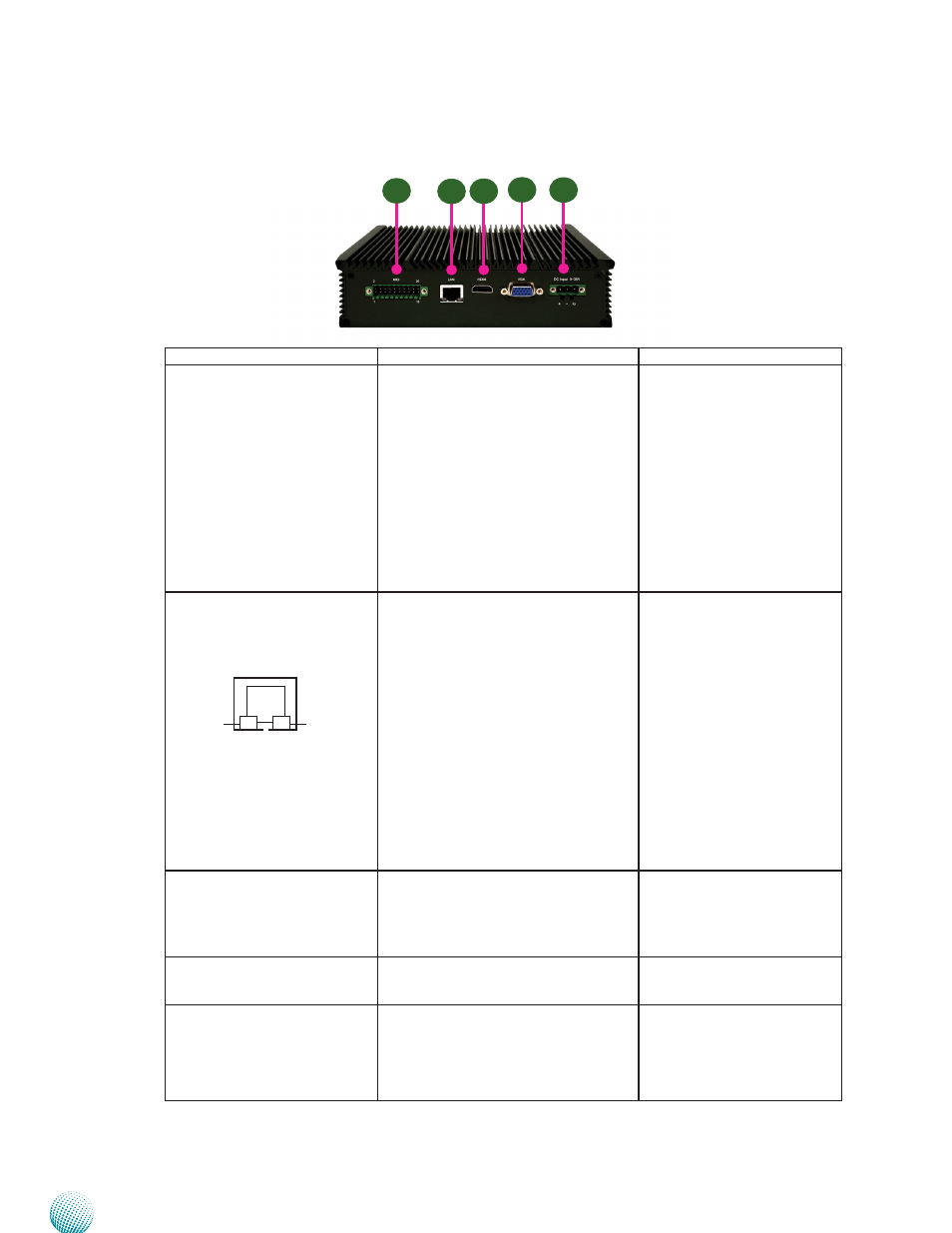
Rear Components
Component
Description
Pin Definition Reference
R1 Multiple-I/O Connector
A 20-pin male connector for the
following functions:
•
4 Digital-In & 4 Digital-output
•
12VDC power output
•
Two Output relay control with
contact current which support
9~36V@ 2A each
•
MCU input detection to wake up
the system automatically
•
One serial communication port
MIO2 on page 20
F3 One 10/100/1000Mbps LAN
ports
One RJ-45 (provided by Intel i210IT)
jacks with LED indicators as described
below
LINK/ACT (Yellow)
•
On/Flashing: The port is linking
and active in data transmission.
•
Off: The port is not linking.
SPEED (Green/Amber)
•
Amber: The connection speed is
1000Mbps.
•
Green: The connection speed is
100Mbps
•
Off: The connection speed is
10Mbps.
R2 HDMI Port (‡)
A HDMI port which is provided
by Intel HD graphics (resolution:
1920x1080@60Hz). There is also an
internal Audio pin header for HD Audio
MIC-in/Line-out
HDMI1 on page 19
R4 VGA Port (‡)
It connects an external VGA
monitor or projector (resolution:
1600x1200@60Hz)
VGA1 on page 19
R6 Power-In (DC)
Power-in with ignition support. The
system support a wide range of power
input +9~+36V including the prevalent
12V and 24V vehicular power system.
It has a 2KV ESD protection on the DC
input and ignition line.
PRJK1 on page 21
R1
R2
R3
R4
R5
LINK/ACT
SPEED