Chapter 3, Board layout – Lanner LVC-2000 User Manual
Page 19
19
Board Layout
Chapter 3
Embedded and Industrial Computing
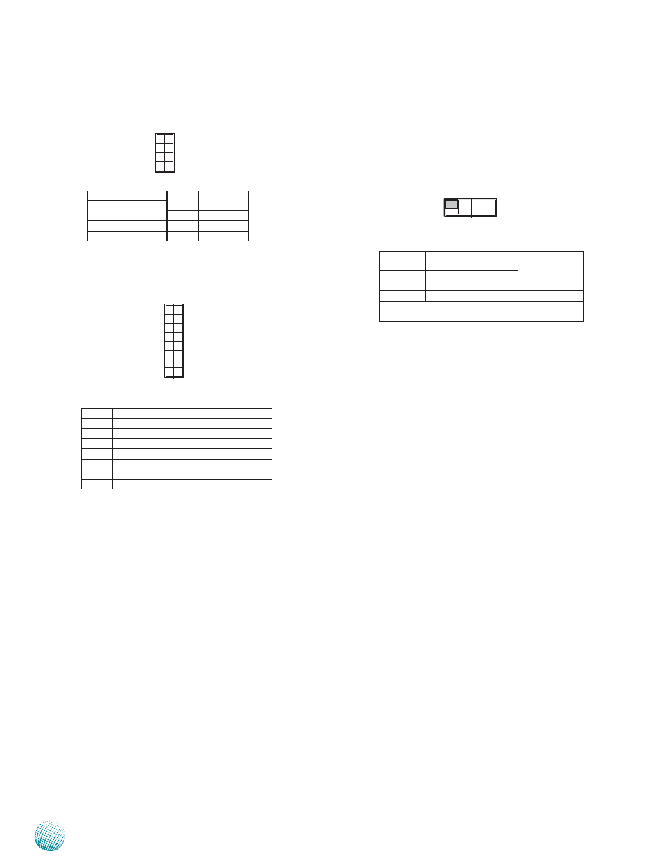
Select MCU Detect Function for power ignition
behavior (SW1):
The functions of the above jumpers are further explained
here.
1.
Power Good Detection: A power-good signal
from the main board will be sent to the ignition
controller so that the ignition controller can
decide or alter the power state upon the following
instances. (Refer to the flow chart in Chapter 4):
•
Power-on instance
•
Power-good signal turned-low instance
2.
Low Voltage Detection: Turn on this switch to
enable the automatic detection of low voltage
state of the battery. It will automatically turn
off the system when low voltage state has been
detected (Note: the low-voltage condition needs
to remain 30 seconds continually). The voltage
level can be set in the Ignition System Manager
(ISM) which is provided by Lanner as a sample
code for functions on the power ignition module.
The default setting of this function: Shutdown
Voltage in the ISM is disabled. (Refer to the flow
chart in Chapter 4 and the Using the Ignition
System Manager (ISM) in Appendix A.)
3.
Watchdog: Enable this switch to enable shutdown
after watchdog timer count-down to zero. This is a
programmable function. If there is no program to
control and monitor the watchdog timer, set this
jumper to disabled to avoid abnormal shutdown.
The default time-out value is 300 sec( you will need
an AT command to reset watchdog timer; contact
Lanner rep for this program).
Pin No. Pin Name
1
VCC
3
MDATA
5
KDATA
7
GND
Pin No. Pin Name
2
MCLK
4
NC
6
NC
8
KCLK
1
3
5
7
2
4
6
8
4 3 2 1
SW1
Selector No.
SW1
Ignition Function
1
Power Good Detection
ON: Enable
OFF: Disable
2
Low Voltage Detection
3
Watchdog
4
Programming MCU
Reserved
The default value is ON for selector 1, ON for se-
lector 2, OFF for selector 3, and OFF for selector 4
ON
Pin No.
Signal
Pin No.
Signal
1
BAT_12V_24V
2
K_LINE
3
DO
4
N/A
5
GND_CAN
6
GND_CAN
7
PLTRST_BUF1
8
J1850+/J1708+
9
SIO_SIN3
10
J1850-/J1708-
11
SIO_SOUT3
12
CAN_H/J1939+
13
V5S
14
CAN_L/J1939-
PS/2 Keyboard and Mouse Connector (JKBMS1)
CAN bus Module Connector (CN1)
13
1
14
2